Homage Piece: veneered coffee table


Two views of Graham Sand’s torsion box coffee table veneered in Huon pine with ebony inlay and a base made from solid wenge.
Words, photos and diagrams: Graham Sands
I greatly admired the late Western Australian craftsman Greg Collins. He was internationally renowned
and received many awards for his innovative and artistic woodwork1. When I visited him in his Margaret River workshop he kindly shared with me techniques used to make his beautiful and finely detailed furniture and objects. I was so inspired that I then planned to make a table influenced by him and his body of work.

1. The author with the Huon pine flitches sawn by Greg Collins. The wenge used rests on the torsion box that was veneered for the tabletop.
Later on, after discussing my idea with him, Greg offered me several flitches of figured bird’s eye Huon pine from his personal collection together with some ebony for my table and other projects (photo 1). That was just before I moved to New Zealand. After eight years and staying in contact with Greg, I built up enough courage and skills to make the table using his veneers in my new workshop.
I decided to make a coffee table, the central focus of a living area and home, conversation and relaxation. This would be my first veneering project using Greg’s enthusiastic advice. Sadly Greg passed away after I started, making it all the more important for me to aspire to his high standards and for the table to serve as a reminder of our friendship. I was very conscious of him looking over my shoulder during this project.
In keeping with Greg’s style, a fine ebony inlay borders the Huon pine veneers and both are framed by a solid Huon pine mitred edge. The Huon pine is of a bright golden appearance and the top has the proportions of the golden ratio.
The veneers were laid onto a marine ply torsion box, which Greg suggested. This provides a stable and rigid platform which floats
over an almost black frame. The top is supported only at the corners by wenge legs held in position by a slatted wenge bookshelf underneath. The wenge doesn’t challenge the Huon in any way. Greg often used exotics.
The table is 1225 x 757 x 450mm high, the top is 50mm thick and the legs are 50mm square. The rails are 30 x 50mm and the sixteen slats are 24 x 17mm at approximately 90mm centres, flush with the top of the rails and set 120mm below the underside of the top. Without a veneer press my first step was to make one.
Veneer press
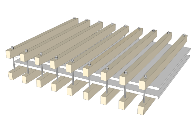
Fig.1 Veneer press caul arrangement.
I decided to make a caul press rather than investing in vacuum, so this was the first part of the project. After studying magazine articles and extensively scanning the internet, I came up with a configuration of nine sets of 65 x 42 x 900mm pine cauls at 150mm centres and two sheets of 1200 x 800 x 19mm MDF (fig.1).

2. M8 dome nuts were glued and screwed onto one end of the veneer press rods.
For clamping pressure I used 18 250mm lengths of M8 threaded rod, each capped with dome nuts (photo 2). Three washers of increasing diameter under each dome nut distribute the force.

3. Captive T-nuts were secured into the bottom of the lower caul.
The other end screws into M8 captive T-nuts secured into the bottom of the lower caul (photo 3). Although M6 rod would have been strong enough, the M8 T-nuts provide a much better bond into the cauls. It is important to oil the thread where it passes through the T-nut, this gives a big increase to the achievable pressure.

4. Measuring the caul curvature required to apply even pressure across its length with a small block placed centrally between two cauls.
The upper cauls have 9mm holes drilled each end and the lower 10mm to house the T-nut and provide clearance for inserting the rods without binding and the bending of the cauls under pressure. To measure the caul curvature required to apply even pressure across its length I clamped a small block centrally between two cauls (photo 4).

5. Bandsaw the curve on the cauls.
I tightened to an equivalent pressure of moderate hand clamping2 giving a deflection of 4mm at each caul end: 20 of 25 torque setting, low gear using my drill/driver. Then with a straightedge I ruled a line 2mm extra to the 4mm end deflection points
and caul centre. After the caul was relieved the line was curved and easily followed all the way with the bandsaw (photo 5). This was then used as a template for the other 17 cauls.
Torsion box
The torsion box is made from 10mm marine ply, and the 24mm high core beams are spaced at 140mm centres. This arrangement was determined after careful consideration of tabletop thickness, weight and strength to span between the legs.

6. Cutting slots for the interlocking torsion box frame.
The core beams interlock each other with slots cut using the sliding table of the router table (photo 6). These were cut in batches to ensure the slots lined up for assembly.

7. The corners of the torsion box were reinforced with ply.
The corners were packed with stacks of plywood cut the same height to provide a solid side grain for fixing the legs (photo 7). The tops of two trestles were set up coplanar using winding sticks and the glue-up was done in stages between sheets of MDF with clamps and weights. I didn’t use the press for this, as it would be difficult to keep it perfectly flat.
Veneer preparation

8. Taping the Huon pine veneers.
The veneers resawn by Greg were 4mm thick ‘providing a durable surface and the potential for re-surfacing’, he had explained. After drum sanding the show side smooth and the other flat they ended up 3mm. The edges of the veneers to be bookmatched were then jointed face-on-back using a track saw with a fine tooth blade.

9. Applying glue to the edges of the veneer leaves.
After aligning the bird’s eye figurings the veneers were pulled together with tape (photo 8), then hinged open
so adhesive could be applied to the edges (photo 9). After hinging the veneers back together more tape was used to keep them tightly together while the glue dried. The remaining veneers were also joined into layons.
Chemistry

10. Mixing the hardener and colloidal silica filler for the West System epoxy.
I had planned to use PVA glue and it probably would have been fine, however, I clearly recall Greg saying to use West System Epoxy. I learnt that a total adhesive thickness of 0.3mm is required for veneering. My table surface is approximately one square metre therefore a quantity of 300ml was required (150ml each surface).

11. The glue has to be the consistency of ‘runny mayonnaise’.
It is important to accurately weigh the quantities for mixing. At a ratio of 1:5, 206 hardener gives an open time of half an hour. After thoroughly mixing in the hardener, colloidal silica filler was gradually added (photo 10) until a ‘runny mayonnaise’ consistency was achieved (photo 11).

12. A roller is the best way to spread the glue evenly.
This prevents the resin soaking through the veneers as without filler the resin is quite thin. West System supply paint roller covers for application at the required thickness (photo 12). The resin was applied to both contacting surfaces.

13. Checking positioning of veneer layon.
I made pencil reference marks under the layon so it could be positioned centrally and parallel on the torsion box (photo 13). The upper MDF sheet of the press was placed on with cling film taped to the underside so any resin seepage would not adhere to it. Both sides of the torsion box were veneered to prevent warping.
Pressing

14. Mating up upper and lower cauls.
The cauls were then fitted together (photo 14), and the rods tightened from the centre cauls out in two rounds up to a torque setting of 21/25, one setting more than when the cauls were made, so pressure is applied right up to the edge (photo 15).

15. Tightening the dome nuts, don’t overdo this.
It is important not to overtighten as (unlike regular clamps) the centre of force of the rods is beyond the edge being clamped2. The veneers remained in the press for 24 hours.
It all worked beautifully – what a relief – so onto the show top. As it happened, after pressing the top, resin was forced through quite a few bird’s eyes and loose knotty bits, which was good, as they were filled and cast in place with the clear resin. The cling film covered MDF sheet came away cleanly leaving them with a level gloss surface.
The sides of the tabletop along with the veneers were then trimmed clean and square with a fine tooth blade track saw, ready for edge treatment.
Ebony inlay
The rough sawn ebony strips from Greg were straight but a little wavy. It would be too dangerous run them on the jointer so I cut reference edges using the track saw which allowed me to thickness plane them and cut 4 x 8mm strips on the bandsaw. Although excessive for inlay, this enabled ease of handling without risk of breaking.
Edge strip

16. Routing a rebate to accept the ebony inlay for the mitred frame for the top.
The ebony strips were glued into rebates routed into Huon pine edging (photo 16) then flushed in the drum sander (photo 17).

17. Huon frame components with inlay fitted are passed through the drum sander.
The ebony was only just long enough for the long sides of the table so every precaution was taken to avoid chipping when cutting the mitres (photo 18).

18. A sacrificial board and tape provided insurance against chipping out when mitring the frame parts.
If that wasn’t worry enough, getting the length right for the mitres to close up nicely made it doubly nerve-wracking.

19. Biscuits were used to strengthen the attachment of the frame to the torsion box.
Biscuits were used to vertically align and secure the edge strips onto the veneered torsion box sides (photo 19). The slots in the torsion box were cut with the biscuit joiner fence sitting on tape to raise the edge slightly for sanding flush later.
Wenge frame

Fig.2 Tenon configuration
Construction of the shelf and legs was quite straightforward using floating tenons for all joints (fig.2).

20. Marking out for the table frame mortises requires precision.
I made sure the machining of the components and marking of mortise positions was precise (photo 20).

21. Frame components were clamped for accurate jointing with the domino machine.
I have a shelf unit fixed to the back of my workbench which serves as a stop for firmly bracing components for cutting mortises accurately (photo 21).

22. A dry fit before assembly is essential.
This was particularly important with the slatted shelf because it determined the positions of the legs, which must line up perfectly with the corners of the top. Throughout the assembly process I test fitted the base to the top to confirm that it was square, flat and the leg/top fit was good (photo 22).
Knock-down

23. Dowel centre markers were used on the legs to locate hole positions for fitting the knock-down leg fittings into the top.
The top can be separated from the legs for finishing and restoration. It was positioned with 10 x 50mm loose tenons (un-glued) then secured to the legs with Hettich Rapid S 8mm diameter fast assembly dowels which expand when tensioned with Hettich Rastex 15 cams (photo 23).

24. The holes for the latter were bored with a portable drill stand clamped to the underside of the top.
Holes in the legs for these fittings were bored with a drill press prior to glue-up. After glue-up I used dowel centre markers to locate positions for the corresponding holes in the top.

25. Assembling the table frame after a dry fit gave the all clear.
These were bored with a portable drill stand clamped to the underside of the top (photo 24). The final assembly went together without any problems (photo 25). The table was professionally finished with a semi gloss two-pack polyurethane.
Overall I’m very happy with the end result, and I now have a lasting and ever-present reminder of a man I admired very much.
I would like to thank Raf Nathan, Damion Fauser, Grant Beck of Adhesive Technologies Ltd and of course the late Greg Collins
for their guidance and encouragement with this project.
1. Greg Collins appeared on the cover of AWR#34. The profile of Greg that appeared in that issue is now on our website.
2. Epoxy resin requires only moderate clamping pressure. For PVA adhesive use firm pressure.
Graham Sands is Wood Review’s illustrator and also a keen woodworker. He has written several stories for AWR. He lives in Titirangi, New Zealand.