Making the Shadow Sideboard
Words and photos: Neil Erasmus
Diagrams: Graham Sands
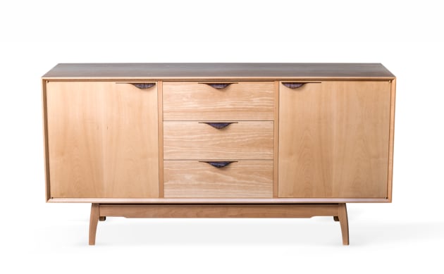
Simple, uncluttered panels are typical of this genre of casework, keeping the look suitably restrained. As such, plain solid panels were made up for the carcase top, bottom, sides, vertical dividers and shelves. This way, wood movement is conveniently catered for without the need for complicated expanding frames. The grain runs in the same plane, allowing for free movement front-to-back.
However, for a uniform look, veneer over a man-made substrate was the only option for the doors. Shop-made sawn veneer made for understated doors that were hung on inconspicuous knife hinges (photo 1). The plain back panel and drawer bases were similarly constructed.

1. Knife hinges were used for an inconspicuous look.
The base is solid wood throughout using simple mortise and tenon, and domino construction techniques. The inside of the unit is finished in nitrocellulose lacquer and the exterior is oil-finished.
Design and planning
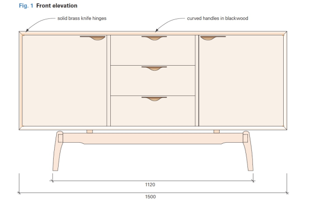
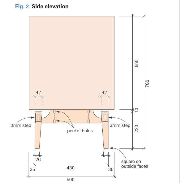
I drew up basic front, side and end elevations to a scale of 1:10 (figs 1, 2). Before I begin the cutting list, I decide what joinery I wish to employ, including the dimensions of those joints. This helps to determine exactly the overall length of each component, including tenons or dovetails. Areas where wood movement may impact are carefully considered.
My cutting list will include overall dimensions of every piece of wood and other material in the piece, and also specify the joinery to be used. I draw the more complex parts with every detail, such as shaping, mortises and tenons, as well as measurements. Any competent maker should be able to exactly reproduce components from these blueprints as every scrap of information is there!


First the carcase
I start with the edge-to-edge joined parts, as the finished carcase provides me with precise measurements for the doors and drawers. The panels were joined from 175–200mm wide stock. Board length permitting, aim for wrap-around grain on the top and sides. The wood for this is machined up and edge-jointed on the surface planer, then shot with a sharp No.7 or 8 handplane to cut through any case-hardening and machine ripples.

2. Bear down firmly when mitring on the tablesaw as any cupping will result in a curved saw-cut.
This alone should provide an excellent joint, but you can use biscuits or short dominos to help align the boards. Once joined and flushed off these parts can be cut to exact sizes, bearing in mind the outer parts are mitred on the tablesaw to these measurements. It is important to bear down firmly when holding them down as any cupping will result in a curved saw-cut (photo 2).
While the glue sets, I busy myself with the back panel and drawer bases. Substrates are cut slightly oversize, as are the veneer layons that are pressed to each face of each panel. After pressing, the back panel can be cut to size. The three sheets of leather may now be pressed onto the drawer bases, and put aside until later. The dimension of the back allows a little slop, about 0.5mm all the way round in a 5mm deep groove.

3. If put aside for a short time, always stack components to allow clear airflow.
The mitres are dominoed, using the flap of the domino machine set at its smallest value, with a 6mm bit set for maximum penetration. To allow for a little side-to-side adjustment upon assembly, cut the sides on the smallest oscillation setting, and the top and bottom on the middle one. Ten equally spaced, matching marks are made on the outside face of each of the corners to align the machine, and the cutting can commence, with the flap bearing down on the outer face of the boards. Be sure to plunge the machine into the wood gradually. Whenever these parts are put aside for a little time, they must always be stacked to allow clear airflow (photo 3).
See Neil Erasmus's article on making right-angled dominos here.

The inside faces of these four components are next grooved to take the backing, which should measure between 7.2 to 8mm thick, depending on the substrate and veneer choices. It’s important to position the inside face of the back 13mm from the back edge of the solid components, and to groove the slot 5mm deep (fig.4).

4. Machining the decorative mitred front edge is a two-step routing operation.
Machining the decorative mitred front edge is a two-step routing operation (photo 4). A 17mm bevel with a 45° bit is first cut, then a rebate routed into the inside corner. The front edges of the two dividers are fixed flush with this rebate, and finish at the groove for the back panel.

5. A ply jig was used to mark positions for the dominos shown cut here.
Next, I cut a rectangular piece of 18mm MDF as a domino jig, sized to match the mid-section where the drawers fit – 473.3 wide x 473 deep. This is marked on either end with domino positions, and placed perfectly in the middle of the top and bottom panels as a positioning stop for the No.8 x 40 dominos that fix the dividers. As before, the slots are nominally sized on the dividers, and enlarged on the top/bottom panels to allow a little leeway (photo 5).

6. Holes drilled 50mm apart for brass shelf supports.
Before assembly holes are drilled to the sides and dividers for the three shelf positions (photo 6).

7. Showing the shelves installed.
These are matched on the magnet positions to the doors (photo 7). The four cleats or drawer runners are now dominoed into the drawer cavity area, and drilled for three screws each. Allowance is made for the carcase to expand/contract, so each runner is fixed at the front, 20mm behind the front edge of the divider, then slot-screwed in the other two positions.

8. Strengthen the area where the knife hinges are fitted so they won’t break out.
The knife hinges are set into the top and bottom panels, but it’s advisable to charge the short-grain where the hinge goes with superglue to convert that small area into ‘plastic’ that won’t break out (photo 8).

9. Assembly begins by positioning the dividers and back panel into the top and bottom panels with epoxy glue before clamping with cauls.
The inside surfaces of the cabinet and back may now be sanded, joints masked off, and finished in shellac or spray-on lacquer. The parts of the hinges that fit to the carcase are now drilled and screwed in place. The seven parts of the carcase are now ready to assemble. The dividers and back are first positioned into the top and bottom panels with epoxy glue, then clamped with cauls (photo 9).

10. If the panel binds in the groove, you can relieve the sides with a modified side rebate plane.
The back panel may require a little ‘fettling’ to allow it to slide easily (photo 10). After this sets, the end panels can be glued in place. To make this easier, I made up four special cauls which direct the clamping pressure at right angles to the mitre (photo 11). Measure the diagonals for the squareness and adjust if necessary.
11. Four cauls were made to clamp the mitres at right angles.
The base

12. The legs and rails are then shaped on the bandsaw and spindle moulder.
The legs are tapered then orientated for position and marked. For the inside face tapers I made a simple bandsaw jig (photo 12). Each offcut was taped back onto the leg to keep it properly angled while shaping. The legs and rails were shaped on the bandsaw and spindle moulder, and then jointed.

13. The short rails are mortised with the help of 2 x 20mm spacers and a 1.5mm thick steel rule for three slots that matched in the long rails.
The short rails are mortised with the domino with the help of 2 x 20mm spacers and a 1.5mm thick steel rule to give three equally spaced slots that are matched in the long rails to suit the 10 x 50 domino (photo 13). The steel rule raises the short rail to give it a 1.5mm step between it and the underside of the long rail.

14. The ends of the long rails are tenoned to fit mortises in the legs.
The top edge of the short rail is curved at each end to allow it to meet the long rail with a similar 1.5mm step, and to elevate the entire assembly so the legs are 10mm clear of the carcase.

15. The 10mm pocket will allow some flexing of the screws as the carcase moves seasonally.
The ends of the long rails are tenoned to fit mortises in the legs (photo 14). The short rails are drilled with 10mm screw clearance holes (photo 15), two sets in each to fix the base to the carcase. The 10mm pocket allows some flexing of the screws as the carcase moves seasonally.

16. Base components ready for assembly.

17. Before veneering the doors three magnets are fitted into the inside faces. Several 0.5mm spacers are used to fit the doors to the carcase.
The doors
I then proceed with the doors, drilling holes in the substrate for the magnets, and routing into edges where the hinges fit to provide solid wood blocks for the hinge screws to bite into (photo 17). These are glued in place, flushed off, and the mitred lippings applied. These are glued on and held in place with masking tape, and once set planed flush.
Before the veneer layons are pressed on, three 10 x 5mm magnets are fitted into the inside face of each door. Opposing magnets are placed behind a veneer in the edges of the shelves.
Make sure you mark the doors for orientation. Once the veneer layons have been flushed off, they are now ready to fit to the carcase. I use several 0.5mm spacers to aid me in this (150mm steel rules are ideal), hand planing where necessary. I aim for 0.5mm on the top and sides, and up to 1mm at the bottom edge. Once I’m satisfied with the fit, the hinges are set into the top and bottom edges.
The drawers
The two top drawers each have a 20mm extension to the bottom edge of their fronts to cover the runners that support them The drawer fronts are half-blind dovetailed to their sides, while the backs are dominoed into the sides with No.4 dominos – remember, I was after an affordable piece of furniture with uncompromised strength.
The drawer bases will finish at a thickness of 6.5mm with the leather. The 6.5mm wide grooves in the sides and fronts start at 9mm from the bottom edges of the sides, and are 5mm deep in the sides, and 10mm deep in the front. The half-dovetail pins on the bottom edges of the drawer fronts must be sized to be about 1mm clear of the groove. The finished drawers are hand- planed to fit snugly to their respective openings, leaving a 2mm gap at the top of each to allow expansion.

18. The handles are made up from five layers of 0.6mm veneers cut with the grain of each running at 90°.
The handles
Five layers of 0.6mm veneers made a combined thickness of 3.2mm, a perfect fit in a groove cut with a standard 1/8" router cutter. Fifteen veneers are cut at 150 x 35mm, and ten at 35 x 150mm, ensuring a good cross-ply for the strength required – the first value being the along-the-grain dimension (photo 18).
I chose highly figured material on the outer veneer and then, to prevent them from snapping as they bend in the press, stretched over two pieces of clear packaging tape. Each set of five cross-plies, glued and wrapped in cling- wrap is pressed over a quarter-round, 1" radius former in a vacuum press, then shaped and cut to fit a 140mm groove in each drawer front and door.

19. Grooves for the laminated pulls are routed 7mm from the top edges of each drawer and door and to a depth of 7 or 8mm.
The grooves, set down 7mm from the top edges of the drawers and door, are router-cut using a 1/8" down-cut spiral cutter and fence to a depth of 7 or 8mm (photo 19). The handles were angled in by 13° to keep them closer to the surface.

20. The handles were angled at 13° and glued in with epoxy.
A wedge made to that angle was double-side taped to the router base. Once all the grooves are cut, it’s just a matter of squaring the ends of each groove, and setting the straight edge of each handle into it with epoxy (photo 20).
For me the processes described here simplified the making of this cabinet, but will still ensure a sound construction with appropriate allowances made for seasonal movement.
First published in Australian Wood Review, issue 87.
Neil Erasmus is a furniture designer/maker in Perth, WA.