Calibrating a sliding tablesaw

Words and photos: David Luckensmeyer
Why a slider?
I made the transition from a cabinet tablesaw to a sliding tablesaw (or ‘slider’) and never looked back. Everything a conventional saw can do – whether contractor, hybrid, or cabinet saw – a slider can do. In fact, many cutting operations are easier, more accurate, and safer on a slider. The only drawbacks are the footprint size and the cost of purchase.
The advice given in this article is general in nature, and I cannot stress enough that sliders are complex machines. Hopefully the calibration process for your machine will consist mostly of alignment verifications. But if you uncover some serious calibration issues, you should involve the technical support representative for your make and model of slider.
Verification tools
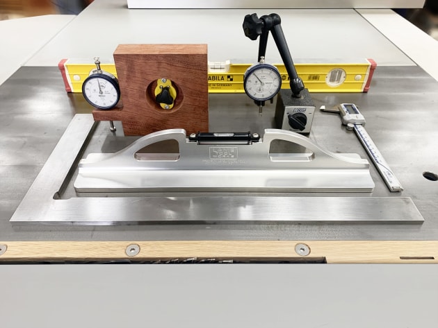
1. Calibration tools from front: precision machinist square, Lamb Tool Works precision level, Canadian- made Oneway multi-gauge in timber shopmade holder, dial indicator and magnetic stand, digital calipers, standard short level with machined edges.
Photo 1 above shows the tools that I like to use when verifying the calibration of my sliding tablesaw. You may be surprised not to see a precision straightedge and feeler gauges. Straightedges are expensive, and the verification methods shared below are easier to employ. The tools discussed may be difficult to source but they are all available online in metric or imperial, hence measurements are given in both systems.
Before starting, make sure your saw is disabled (e.g. activate the emergency stop). In the photos the guard has been removed for photo clarity.
Starting from flat
The starting reference is the main cast- iron machine table. The sliding table, blade, and rip fence are all aligned in relation to that surface. And the easiest way to check a milled surface for flat is by using a precision level.
The gold standard is the LS Starrett master precision level, but it is priced accordingly. Less expensive models are available but check the accuracy standard before purchase. The sensitivity of the level should be 0.025mm per 300mm or better. I have a US-made Lamb Tool Works precision level that, at around 400mm, is the perfect length for checking cast-iron tables. It is accurate to 0.001" (one thousandth of an inch) per foot, or about 0.025mm per 300mm.

2. Both sliding and cast-iron tables need checking for level. On my saw, the precision level shows an acceptable difference of 0.05mm (0.002"). The ground and graduated vial in a precision level is so sensitive that it takes several seconds for the bubble to stop moving.
If the readings of the level at the front and back edges of the cast-iron table agree, then the casting is flat and has no twist. Similarly, when the level is placed across the width of the sliding table itself, and the level reading is the same, then we know that the sliding table is coplanar (parallel) with the cast-iron table (photo 2).
Verifying the sliding table alignment
Adjustment procedures will differ according to brands and models, but put simply, the sliding table must be slightly higher than the cast-iron table. If the slider dips below at any point along its movement, then material held or clamped onto the sliding table will drag on the casting.
Many saw makers aim for a calibration height of 0.20–0.25mm (0.008–0.010"), which is fine for kitchen manufacturers, but for fine furniture makers the relative height of the sliding table should be about 0.10mm (0.004") above the cast-iron table. Such a tolerance is important for non-through cuts, like grooves and trenches, sliding dovetails, narrow rip cuts to the right of the blade, and so forth.

3. Dial indicators come with different ranges and sensitivities, with or without a lug on the back and with interchangeable tips. A standard indicator is accurate to 0.01mm, and with a range of around 20mm, is ideal.

4. After the dial indicator has been zeroed out on the cast-iron table, it may be employed to verify that the sliding table is higher by 0.10mm (0.004").
A simple and accurate way to check the sliding table alignment involves using three dial indicators on stands for a dynamic verification of slider behaviour through its full stroke. Each indicator is zeroed out on a known flat surface, and then carefully moved to indicate from the cast-iron table to the surface of the slider (photo 5).

5. For the dynamic verification, it is not uncommon to see height readings beyond 0.10mm (0.004"). Readings of 0.15– 0.20mm (0.006–0.008") are acceptable; beyond that, ask your dealer.
Sliding table toe-out

It is also important to check the sliding table toe-out relative to the blade. The trajectory of the sliding table should drift away from the sawblade (fig.1). If the toe- out is inadequate or excessive, the trailing edge of the sawblade will cut or burn the material as it passes by (photo 6).

6. The ideal sliding table toe-out is 0.05–0.10mm (0.002–0.004") over a distance of 250–300mm. It does not have to be exact. Make sure to use light pressure when clamping to avoid distorting the blade.
Using a dial indicator to indicate to the same tooth on the blade, first at the front and then at the back will yield a relative measurement. But using a machinist square or a standard short level with machined edges to average out all the teeth into a flat registration will yield more accurate results. We can verify toe-out by indicating from the sliding table to the reference surface of the square/level, while moving the sliding table.
Outrigger table verification
An outrigger table provides a marvellous way of supporting large items for sizing. It also provides extensive support for crosscutting long stock. Here is the verification process:

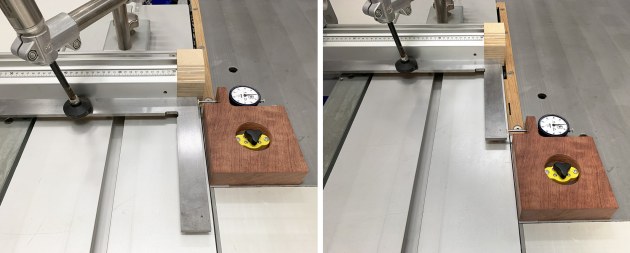
7. Here I’m using a standard level to support the precision level. A straight piece of timber would also be acceptable.
A. With the outrigger support arm perpendicular to the slider, make sure the outrigger is level and coplanar with the sliding table. This can be verified using a precision level suitably supported across the outrigger and sliding table (photo 7). Adjustments are machine specific and involve changing the height of the vertical support arm, or the connection to the sliding table, or both.

8. Dynamic adjustments are tricky and should not be attempted lightly. Go slowly, and move the slider throughout its stroke repeatedly, watching how minute adjustments change the outrigger table’s height.
B. A dynamic verification is required to check that the outrigger remains level throughout the stroke of the sliding table. If it doesn’t, the support arm pivot point will need to be adjusted. The axle must be exactly perpendicular to the sliding table, in both axes (photo 8). Otherwise, the outrigger will not remain coplanar through the slider stroke. Again, the adjustments are machine specific, but usually involve loosening and tightening grub screws that hold the axle in position.
Arbor run-out

9. I am using a Noga magnetic stand to hold the dial indicator. The single adjustment knob tightens all the knuckle joints simultaneously making it very easy to adjust the indicator’s position.
A dial indicator and an adjustable indicator holder with a magnetic base are required to check for run-out (which is the rotation of the arbor in an eccentric manner). Position and lock the holder, adjust and zero out the dial indicator, and rotate the arbor by hand (photo 9). Any eccentricity should be 0.025mm (0.001") or less – if the arbor is out by more than 0.025mm, you need to seek assistance.
Blade height and angle
Sawblades are notoriously difficult to check for height and angle: the irregularly shaped carbide teeth often get in the way of squares, and some sawblade bodies are hollow ground and thus not flat. Consequently, it is usually better to measure the results rather than the blades themselves.

10. Keep in mind that blades have slightly different diameters, and this calibration process should be carried out after blade changes and sharpening.
A combination of methods first involves lowering the blade level with the cast-iron table. A piece of timber can be positioned over the blade slot and the blade adjusted until its teeth are barely touching the timber. Or the piece of timber can be swapped for a dial indicator (photo 10). Once satisfied, the height readout, whether analogue or digital, can be zeroed out. Then verify the depth of cut by making a groove in a piece of scrap, and measuring with digital calipers.

11. Thicker timber cross-sections are easier to register together for visual checks of the blade angle. Using a clamp is a helpful tip.
For 90° calibration, cut a piece of timber in half, turn over one half, and put the cut faces together and check the results. One edge of a machinist square or straightedge will reveal if the two pieces form a perfect straight (photo 11).

12. Longer pieces of timber are helpful here since they magnify any error.
For 45°, use a similar procedure of cutting two pieces of timber at 45°, and putting the cut faces together. This time instead of checking for straight, we’re checking for square (photo 12).
Rip fence calibration

13, 14. The ideal rip fence toe-out is the same as for the slider: approximately 0.05– 0.10mm (0.002–0.004") over 250–300mm.
When it comes to rip fences, the calibration for width comes to mind. But first the rip fence needs to have a toe-out of approximately 0.05–0.10mm (0.002–0.004") over 250– 300mm (photos 13, 14); otherwise the back of the blade will drag on the material being ripped.
Once the correct toe-out is verified, a square can be used to check the face of the fence in relation to the cast-iron table, and a piece of scrap material can be ripped, and the results measured with digital calipers for width. All adjustments for the rip fence are machine specific.
Riving knife set-up
A riving knife is important for safe work because a closing kerf on a rip cut is dangerous. Unlike many conventional saws, most sliding tablesaws have a riving knife that is adjustable for height and moves in line with the blade for all angled cuts.
The body of the riving knife must be narrower than the kerf width, but wider than the blade body. For example, for a typical blade with a 3.2mm kerf, and a 2.2mm blade body, a 2.8–3mm thick riving knife is perfect. A 4mm riving knife would bind in the kerf, and a 2mm riving knife would fail to keep a closing kerf from binding on the blade.

15. The riving knife should be adjusted just below the top of the blade, with a gap of 10mm between the riving knife and the back of the blade.
It takes time to get a riving knife properly aligned behind the blade (photo 15). Raise the blade all the
way and use a small ruler to verify the alignment down low (near the slider) and up high (at the top of the blade). While making adjustments, ensure the riving knife is in the same plane as the blade, and is not twisted one way or the other.
Calibration for square
The five-sided method for checking for square is prone to inaccuracy and takes too long. Using a precision machinist square and dial indicator is easier, faster, and a more accurate way to square crosscut fences.
16, 17. When the indicator stays the same, the crosscut fence is calibrated square to the direction of the sliding table and will yield accurate 90° cuts. Square to the direction of the slider is what’s important here, not square to the blade, since this compensates for slider toe-out.
With your square registered against the crosscut fence, position a dial indicator near the blade, and secure it to the cast-iron table. Now indicate to the edge of the square and move the sliding table. The fence will yield square cuts when the indicator stays the same along the edge of the square (photos 16, 17). Unlike mitre gauges, the crosscut fence registration is usually located on the end of the outrigger and therefore capable of very accurate calibration.
Crosscut stop calibration
Sliding tablesaws come with at least one stop, and some have two or more. The first stop is best calibrated using digital calipers. Move the stop as close to the blade as possible. If the stop does not come within 150mm of the blade, use a machinist block (e.g. 25–50–100mm) to get closer, or invest in larger digital calipers.

18. Digital calipers are essential measurement tools even if your saw does not have DRO. Using precise dimensions will usually lead to more accurate work.
Take a piece of scrap and cut one end square and then cut to length (e.g. 140mm) using the crosscut stop (and block if required). Measure precisely with digital calipers and calibrate the stop using the method appropriate for your saw (analogue or digital) (photo 18).
If your machine has a second stop, first clamp a longer piece of scrap to the slider and cut to a precise length using the first stop (say 600mm). Then move the first stop out of the way without disturbing the clamped piece of wood you just cut. Finally, move the second stop against the end of the piece of wood, and calibrate to 600mm.
For telescoping stops, we may need to use two pieces of timber of known length. For my machine, the telescoping stop is beyond 1800mm, so I use two pieces of material precisely cut to one metre each, and then calibrate my final stop at two metres.
Scoring blade adjustment

19. Scoring blades can be difficult to see when running, so extra care is required. The scoring blade pictured here is parked below table.
The scoring blade is a small, secondary blade directly in front of the main blade and fitted to most (but not all) sliding tablesaws (photo 19). Its purpose is to reduce or eliminate chip-out (on the underneath side) which often accompanies cutting manufactured materials. I also find it useful for cutting hardwood species prone to splintering. I prefer to adjust my scorer exactly to the width of my main blade.

20. Pictured is a progression of cuts showing the relative thickness and lateral position of main and scoring blades, from misaligned (left) to perfectly calibrated (right).
Scoring blade assemblies can be one- piece non-adjustable, or two-piece with various adjustment mechanisms for width (screw, spring, shims), and may come with different teeth shape options and blade diameters. The blade or blades rotate at much greater speeds (often in excess of 20,000rpm) and in the opposite direction of the main blade, which means they can unexpectedly pull the material forward into the main blade. Beware! digital calipers to measure the kerf produced by the scoring blade and adjust as necessary to match the main blade. Once that’s done, the lateral adjustment is by trial and error. Finally, set the height to approximately 2mm.
In a following article we’ll look at different methods of work that apply to sliders and especially how they compare to working with a conventional saw.
With thanks to David P. Best, a master woodworker whose expertise in machinery is unparalleled. Much of what appears here is due to his inspiration, see his album at flickr. com
David Luckensmeyer is a Brisbane based woodworker and furniture maker, see www.luckensmeyer.com. au and Instagram @luckensmeyer