Redesigning Maloof

Robert Howard in his South Brisbane studio. Photo: Linda Nathan
Words and process photos: Robert Howard
Diagrams: Graham Sands
I had the great good fortune to visit Sam Maloof’s workshop twice in 1980 and 1981, while I was living and working in Los Angeles. That was my introduction to his chairs, and, in particular, to his well known leg joints.
It was not until about 1984, while I was living in Germany, that I was able to use that experience while designing my own chair. It was my intention to use Sam’s joints when the time came to build my first prototype. Although I did not know it at the time, it would be 1990–91 before that happened, because, at that time I had not made a single piece of proper furniture in my life. I had to learn to be a woodworker first.
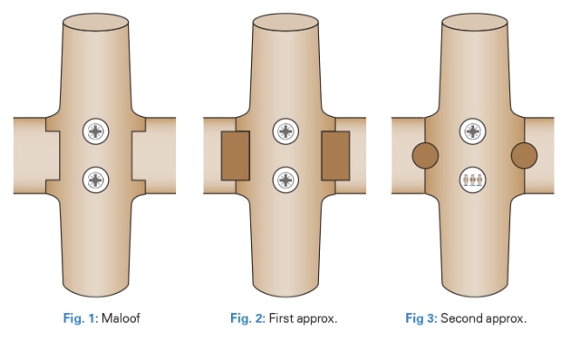
The Maloof joint for the front leg of his chairs was quite straightforward (fig.1), and did not require any special tooling. The leg was at 90° to the seat, and easily cut using a tablesaw and a router. The back leg, however, was only square to the seat in side elevation. In the front elevation it had a few degrees of cant, and to cut this, Sam used two custom made router bits, one at 90° plus the cant angle, and the other 90° minus the cant angle.
(Making the ‘redesigned’ joint is illustrated step by step in photos 1–16. The joint shown is only angled to the seat in one direction, and is square in the other, but it could just as easily been angled in both.)

1. These two pieces of wood represent the seat block (right), and the leg after bandsawing to shape and size. The housing in the seat has been cut to fit the leg at the required angles and depth (about two-thirds of the leg is housed). Do not undercut the sides of the housing as this might show after final sculpting.
When I was designing my own chair, one of my explicit desires was to not make any design compromises in order to make the chair easier to build. There were many consequences of this decision. In particular, none of the legs were square to the seat in either front or side elevation, and although that changed as my design evolved, in the beginning it determined the design of my leg joints.

2. The model shows a ‘leg’ fitted in a ‘housing’.
If I was to use the Maloof joint, it would mean two, three or even four sets of customised router bits to create all the rebates in the joints, and a complex dance of bit changing when making a complete chair. Worse, the expense of the bits would make me reluctant to change any joint angle in the future, so I would be hobbling the evolution of the design right from the beginning.

3. Waste is bandsawn off leg to allow space for sculpted radii. A hole is bored and drilled to take 12g screw. There needs to be room for a gap between screw head and plug after final gluing, otherwise wood movement will pop the plug.
I pushed on regardless, and decided that I would simply do without the rebates around the housings in the seat block, and instead house the seat block in two dados cut into the sides of the legs. This I finally did on the first chair I made – a rocking chair made from coachwood.
Designing and building a chair like this presents a seemingly endless procession of problems to be dealt with, and overall I was satisfied with the result at the time. I was also aware that my joint design was not the solution I hoped it would be.

4. Leg marked out for shaping, and for sculpting the joint.
One of the many beautiful features of the Maloof chairs was the way the components flowed seamlessly into each other. In the leg joints this flow was facilitated by a sculpted radius where the different components met each other. I had no radius in my joint and did not know then how to get one without the Maloof rebate, and the joint was not strong enough, or pretty enough either.

5. Leg after shaping with drawknife and spokeshave.
It did not take long to find a possible solution. As you can see from fig.2, the Maloof joint could be approximated using a simple housed joint with two keys fitted into keyways cut into the seat blank on one side, and the chair leg on the other. These keys would lock the legs in place. With great excitement, I began work on another chair, this one a carver chair made from New Zealand beech.

6. #9 gouge (about 10mm or 3/8 inch) used to sculpt radii on leg.
Once more my hopes were dashed. The idea worked well enough. However, the cutting of the keyways in the seat block proved diabolically difficult in practice, as one keyway in each joint had to be cut against the grain in just about the worst orientation possible. Once more I was stumped.

7. Sculpting finished with rasp.
The solution to my problem was such a profound epiphany that I still remember with vivid clarity exactly where I was and what I was doing when the idea hit me. I was sitting quietly, waiting for my young son to go to sleep, when I realised that the keys in the leg joints did not have to be square or rectilinear. They could be round, and the keyways could be drilled, after the legs were glued and screwed in place. Problem solved.

8. Final fit. On a real chair this would now be glued.
It still amazes me that the solution was so simple, but so difficult to arrive at. I do believe that this joint is more versatile, and stronger, than the Maloof joint, and about as simple to make. And it does not require any custom made router bits, or a router at all, and that is always a big plus in my book.
Robert Howard is a woodworker and sculptor who lives in Brisbane. He teaches regular woodcarving classes from his studio.

9. Setup in drill press to drill for dowels, along the glue line.

10. Turning dowels, with flared ends for tight, final fit in holes. Cut to length for two dowels.

11. Dowels in place.

12. Dowels cleaned up.

13. Sculpting the seat.

14. Finished joint.

15. Showing how the finished joint fits together.

16. This is how the leg joints look after sculpting, sanding and polishing.