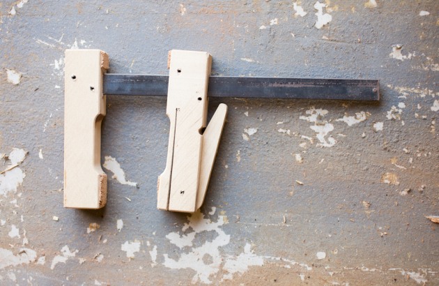
Make your own cam clamps
Words: Joel Dubbeld
Photos: Megan Marano Kersh
Diagrams: Bill Anderson
My career working with wood and building furniture had run many years before I discovered how versatile wooden cam clamps could be. After a colleague brought some German Klemmsia Zwinge clamps into my workshop, I quickly became a convert to this simple, lightweight design.
The cam action allows these clamps to be placed adjacent to each other. By contrast, screw clamps require space to grip the handle when tightening. I also appreciate the fact they are non-marking and cannot be over-tightened. Their light weight is beneficial when a number of them are used on a single project. Finally, because they can be shop-made from readily available materials, their cost is low.
As a caution, there are situations when I don’t favour cam clamps, particularly if great pressure is required. Also, I don’t use them when vibration might cause the cam to loosen. For example, I would never use one to secure a jig on a tablesaw — should the cam shake loose at a crucial moment and release the clamp, a safety hazard or flawed cut could result.
Matched to the right task, it’s not uncommon for me to have up to a hundred of them in use. They have been especially valuable during the ukulele and guitar building courses run from my shop and I see cam clamps as an important part of anyone’s workshop.
Select strong but flexible wood
The clamp faces must be strong against compression and flexible along the lower jaw kerf line to permit the clamp action movement. My choice was to use Tasmanian sassafras shown but I also have American white ash that would work well. Avoid soft species because the jaws could deform under pressure. Brittle timbers could fracture at the critical point at the bar end of the kerf line. Oily woods may inhibit a secure grip of the cam.
Any size you like
An important benefit of this clamp design is that it can easily be scaled up in size. Luthiers often make them with jaws extending to 300mm. The clamps I describe here have jaws 150 x 35 x 25mm. I made the bar length 240mm and as it will be subjected to relatively low bending forces, black mild steel flat bar 20 x 5mm is suitable and available from steel merchants.

Shape the jaws
Rip and dimension the jaws and then dock them to length. Mark the length of the clamp face at one end (35mm) and then mark a length in from the bar end that is three times the bar width (60mm).

Mark out the scalloped recess to 6mm deep between these two points and follow the line on the bandsaw ( fig.1). Clean off the saw marks. For a large production run, flush-cut routing with a template can ease this step. A small chamfer on all the edges is a nice touch and can be applied at this time. Identify half the pieces as upper jaws.
Cut through mortises for the bar
Each jaw will have a through mortise for the bar. Align the mortise one bar-width in from the end. Cut the upper jaw mortise precisely to match the bar dimensions and yield a snug fit (20 x 5mm). The mortise needs to allow the bar to be pounded home without splitting the wood. The mortise on the lower jaw will be larger (25 x 6mm) to allow easy travel of the lower jaw.

The required mortise is too narrow for my mortise cutter so I used a domino machine with two cuts for each mortise — one penetrating from each side.

Drilling out the bulk of the mortise and finishing it off with chisels and a file is another method that would work.

I created a custom file from a spare piece of steel bar to finish the mortises.
Drill pin holes on the lower jaw
Drill four 4mm pin holes on the lower jaw as shown in fig.1. Again, a prepared jig is valuable for quick and accurate marking on large production runs. Two holes will take high tensile steel spring pins to support the jaw on the bar. I get mine from Boltmasters but they should be available from any fixings supplier. The hole that acts as a pivot for the cam lever will also be pinned. The hole that stops the kerf cut will remain blank.
At this time, drill a pilot hole on the top of the jaw for a screw (8g x 20mm) to be placed between the bar mortise and the pin hole at the end of the kerf line. This screw reinforces the jaw to prevent breakage when the lower jaw arm is flexed.
Create a recess slot for the cam

The cam sits in a slot on the bottom of the lower jaw. A dado blade is ideal or multiple passes with a rip blade will suffice. Set the blade height to 25mm. Allow the cut to penetrate 75mm into the jaw, leaving a straight slot with a rounded end that will accommodate rotation of the cam. The opening on my tablesaw is not wide enough for the dado blade so I mounted one in my shaper. The cut is the same, but it is just done horizontally rather than vertically as it would be on the tablesaw. A machined slot is shown above.
Cut the kerf strip

On the lower jaw, use the bandsaw to cut the kerf strip into the pin hole. This is a critical cut. If the flexible arm at the top of the jaw is too thin then the jaw arm risks breakage. If it is too thick then the arm may not be flexible enough and may split. Different timbers may require different settings. In this example, the maximum thickness of the jaw arm (at the scalloped recess) was 5mm. Add the screw to strengthen the jaw.

Create the cams
Numerous methods could be used to create the cams. For my bulk production run I created a cam-shaped blank from a 110 x 200 x 30mm block. Orient the grain parallel to the 110mm edge (fig.2). Pass a 15mm radius rounding-over router bit over both sides of one end to create the round top end of the cam. Pass a smaller 6mm beading bit over one corner of the opposite end.

To complete the cam shape, use an angled blade on the tablesaw to cut one side tangent to the top and bottom curves. Then, rip individual cams to thickness from the blank on the circular saw. Retract the saw fence behind the blade’s leading edge or attach a spacer block to the fence to ensure ripped cams do not get trapped between the blade and the fence (see above).

Check the fit of the cam into the jaw slot.

Drill a 4mm hole in each cam, offset as shown in fig.3 and fig.4. Too much offset and the cam will deliver excessive clamping force and will be difficult to use. Too little offset and no pressure will be delivered to the lower jaw arm.
Drill a 4mm hole in the lower jaw for the cam. Consider two factors when locating this hole. First, have the hole far enough back from the clamp end so the cam will not protrude from the jaw’s end. This permits clamps to sit end- to-end across from each other without interference from the cam. Secondly, position the hole in the jaw such that the cam will move the jaw arm when the cam is turned, but leave the jaw arm relaxed when the cam is neutral. Use a steel spring pin to secure the cam into the lower jaw.
Install the jaws on the steel bar
The mortise in the top jaw was purposefully made tight. Apply a little wax or soap to one end of the steel bar and use a hammer to drive it fully into the upper jaw. Drill two 4mm holes through the upper jaw and the bar as shown. Drive in steel spring pins to fasten this joint.
The mortise on the lower jaw allows movement of the jaw along the bar. Two steel spring pins drilled through the lower jaw just outside the bar hold the lower jaw perpendicular to the bar when the clamp is relaxed and hold the jaw secure to the bar when it is under clamping pressure.
Secure the lower jaw to the bar with a round head rivet at the base of the steel bar. A layer of 2mm thick cork or leather glued to the clamping surface on each jaw is a nice final touch to ensure the clamps do not mar a surface when in use.
Using jigs to hasten the method described here, I have made over 200 of these valuable clamps. While the old adage about never having enough clamps may be true, I’m not saying you should rush out and make as many as I did. Try four to six — my guess is that you too will become a convert to these helpful tools in your workshop.
First published in Australian Wood Review, issue 85, 2014.
Joel Dubbeld designs and makes furniture and cabinetry in Townsville, Qld trading as Studio Dubbeld. He also teaches woodwork and luthiery. Learn more at studiodubbeld.com