Linda Fredheim: Making a veneered hall table
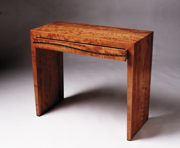
Linda Fredheim’s Nothofagus table is a torsion box construction veneered in figured myrtle with patinated and engraved copper detailing on the drawer front.
Words and photos: Linda Fredheim
The first year furniture design students at the School of Art in Hobart where I teach had been working on designing and making an entrance piece, so I thought I would set myself the same brief. I always start designing by sketching on paper to work up ideas. I wanted the piece to be aesthetically restrained and elegant, but to have some detailing that would add interest.
Those who use and admire timber, often forget where the timber comes from—trees within the forest—and I wanted to suggest this by subtly referencing the delicate dark glossy leaves of the myrtle, and the effect of the light as it filters through the forest canopy. With this in mind I decided to incorporate a patinated and engraved copper strip to add a subtle visual texture. I also felt the flat surface of a table would highlight the grain of the figured board I had been sent.

Figure 1: Dimensions in millimetres
Once I have developed a design by sketching I usually refine the dimensions on the computer to produce some working drawings, and in this case I made a virtual model of the piece. Sometimes an actual scale model or full size mock up is more useful, but after some time looking at the ‘model’ and a full size drawing of the front elevation, I was pretty confident the proportions were okay.
Preparing the wood
I checked the width of the board arrived and made some final adjustments to the design. The thickness of the board would allow me to resaw it into five ‘veneers’, and leave enough for a solid drawer front. I chalked out where the board would be docked, leaving enough at each end to avoid any splits.

1. Bandsawing the veneers. The board initially measured 2600 x 230 x 28mm.
The end of the docked sections were marked so the timber could be reassembled after resawing and sanding. I mark all the docked sections in the same way on the same end, but vary the markings to number 1, 2, 3 (photo 1). This helps with matching and assembling the veneers, and especially so with figured myrtle. The sheen will vary depending on the way the timber is orientated to the light—I have made this error before, and it has severely affected the appearance of the finished object.
Sawing the veneers

2. Five slices sawn. Mark the ends for later matching.
Lightly buzz or plane an edge and face on the docked boards before bandsawing into five slices (photo 2). The timber will usually move a little once any tension has been taken out of it by resawing. My board was quartersawn so it hardly moved at all.

3. A ‘prong’ test will reveal tensions in the wood.
Backsawn timber will often move so much (cupping and bowing) that it can’t be turned into sawn veneers. If in doubt do a ‘prong’ test (photo 3). Cut about 12mm off the end of the board and cut as shown above on a small bandsaw. You will soon see if there is tension in the board that will prevent the board from remaining flat once resawn.
The board I had was very figured and there was a fair bit of chipping when it was buzzed, so I only planed a small amount off to give a flattish surface against the bandsaw fence. You could rebuzz a flat surface each time you take off a slice, but I prefer not to as it leaves me more material, and so I saw each slice, using the previous cut as the surface against the fence. I check that the board stays reasonably flat and only buzz or hand plane it if it gets high or low spots.
Sanding the veneers
The sawn veneers are sanded on both sides on a wide belt sander with an 80 grit belt taking off about 0.3mm each pass. Wide belt sanders are normally adjusted to not sand stock thinner than about 8mm to protect the expensive mat. You could readjust the sander, but we use a backing board—MDF with a piece of old paper belt glued on to prevent the veneer slipping. I aimed for finished veneers of about 3mm.
Making the layons

4. Weighing down the glued layons.
Once I have cut and sanded the veneers I can joint them into layons. The edge of the veneers are planed, glued and then clamped together. In photo 4 the clamps are under the veneers with weights on the top to keep the layon from buckling. Our weights are a selection of short pieces of stainless steel bar, but you can see from the picture that your hand planes can also be useful.
You may need to apply some finger pressure whilst clamping to make sure you get the faces to line up evenly. Tighten the clamps just enough to squeeze out the excess glue. If you tighten too hard the weights won’t be enough to keep the layon from buckling. The sawn veneer layons are then resanded through the wide belt sander down to 2.5mm, with the last couple of passes using a 100 or 120g belt.
Pressing the layons
The layons are glued to one side of a piece of 6mm plywood. The panels will bow once they come out of the press as they are only veneered on one side, but this bow will be cancelled out once two panels are glued to each other via the ribs of the torsion box. The inside panels for the sides were veneered with 2.5mm solid veneers cut from my board, but the inside surface of the top panel is not going to be seen, so I veneered it with 0.6mm veneer.
I shoot the edges of 0.6mm veneers on the tablesaw with our best blade, clamping the veneers between two pieces of 3mm and trimming off enough to create a straight edge that can be taped together. I use Hystick masking tape for this because it doesn’t leave a residue or adhere too well.


5, 6. Vacuum pressing the layons.
I pressed all the panels in the vacuum press using a cross-linking PVA (photos 5, 6). To save glue and time I don’t use a roller tray, but just pour the glue on and roll out. Between pressings wrap the gluey roller in a plastic bag. This way you don’t end up washing a lot of glue down the sink each time and then waiting for your roller cover to dry.
I always put a piece of plastic over the veneered work to keep glue from getting on the expensive rubber membrane and then place a pressboard cut to the same size as the work between the plastic and the membrane, to make sure the pressure on the work is even. (If you are pressing a number of panels of the same size, you can use the other panels or cores as pressboards.)
When using PVA glue in the vacuum press I find you need to be fairly careful once you remove the work from the press. Although the glue has ‘gone off’ the panel and the veneer will be fairly moist and the glue still flexible. As soon as I take it out of the press, I rest it on racking strips on a flat surface to allow both sides to dry evenly and prevent any warping as it dries. With the 0.6mm veneers I also remove any tape as soon as possible after it comes out of the press, peeling it off carefully with the grain.
Making the torsion box

7. Thicknessing with a tapering jig.
Cut veneered plywood panels square and a few millimetres oversize. The ribs for the torsion box are cut to the same length as the panels. For the legs the ribs are tapered 2° using a taper thicknesser jig (photo 7).

8. Showing the ribs on the inside of an outer panel.
I used a piece of 25mm MDF as a solid flat surface to glue up on. The ribs are glued to the inside surface of the outer veneered panels (photo 8). Small blocks of solid wood are cut to size and glued between the ribs. These can be higher than the ribs as they are planed flush, before the inside face plywood/veneer is glued on. You could glue the second face on in the vacuum press, or use G and F clamps over blocks of wood to ensure an even clamping pressure. Plane one edge of each torsion box flat before ripping to width (allow for 2mm solid veneer edging on both sides).
Cutting the mitres
Once the edging was glued on and flushed down, the bottom of the legs were cut square and the top corners mitred. The mitres on the ends of the top are cut at 45°, whereas the mitre on the top of the legs are cut at 43° to take account of the taper. These mitre joints need to be checked for accuracy with the best square you have.
I find the most important thing when cutting mitre joints is to make sure the tablesaw surface is free from debris, and if the panel that is being cut is not perfectly flat it needs to be held down hard on the table. If your work lifts up anywhere the cut will not only not be square, the finished piece will also be longer than you want.
Assembling the torsion boxes

Figure 2
In order to make the drawer construction straightforward, the top 70mm of the inside surface of the ‘legs’ need to be planed/sanded down to provide a square side for the drawer (fig.2).


9,10. Cutting two rows of biscuits.
After marking out and cutting two rows of biscuits (photos 9, 10), I can do a dry assembly of the whole piece to check the proportions and the look (photo 11). This is one of the steps I really look forward to. It is always exciting to see a piece take shape and resemble the original sketches and drawings. It is only once you have the real object in front of you, that you can get a real idea of its proportions.

11. Dry assembly
At this point I decided that a few more millimetres of height would improve the proportions, and that a contrasting strip would visually lift the piece. I had some jarrah offcuts and so made a 6mm strip to glue on the bottom, predrilling for feet.

12. Slipstick feet
I often use ‘slipstick’ feet (photo 12), but set them in 3 or 4 mm so they are not so obvious, but protrude enough to protect the bottom edges of the piece. Glue the strips on with sash clamps using the top dry biscuited in place so as to have a square surface at the other end of the clamp.
Making the drawer shelf
The drawer shelf supports the drawer and also reinforces the table by preventing the legs from moving either in or out, and once the backpiece is glued in the whole structure will be stiffened. However I wanted to keep it fairly thin, so as not to reduce the internal height of the drawer. Consequently I used a piece of 9mm MDF, veneered both sides with some 0.6mm myrtle veneer I had in the workshop. After the front edge of the shelf is edge veneered, it is cut slightly oversize.

13. Rebate cut for laminate strip.
I like to run my drawers on a laminate strip to ensure they run smoothly. I use the router to cut a rebate exactly the right depth for the laminate (photo 13) which is then glued in place as shown (photo 14), after which the shelf is cut to size.

14. Gluing the laminate strip.
Slotting and biscuiting the shelf
You could just biscuit the shelf in place, but I always like to fix my shelves and drawer runners in a shallow 2mm trench. This is partly because the trench itself helps stiffen the structure, but also because the routed groove ensures that the shelf or drawer runner is always parallel, straight and in the correct place.
Depending on the object and its construction and materials, I use screws, slotted screws or cams and dowels to hold the shelf, drawer runner or frame in place. Because this shelf is only 10mm thick I chose biscuits. After a bit of experimentation I found setting a lamello biscuit cutter on ‘S’ gave me the correct depth for a size 20 biscuit allowing for the 2mm groove. I cut the groove first after carefully setting a fence in the correct position and then moved the fence to cut the biscuit slots.
Making the backpiece

15. Biscuiting the backpiece.
The backpiece’s main purpose is to reinforce the table and help to prevent any racking or distortion of the structure by maintaining the 90° relationship of the corners, so it can be made from a piece of 9mm MDF veneered with some of the leftover 2.5mm sawn veneers. Cutting the biscuits on the bottom of the thin panel can be tricky, but clamping a piece of machined timber to the work will give a larger surface to rest the biscuit cutter on (photo 15).
The backpiece is glued last and is fixed with biscuits on the top edge and the bottom of the inside face. Leaving the backpiece out during the main glue up makes it easier to clean the glue out of the inside joints, which is critical if the drawer is going to run smoothly.

16. Clamping the shelf, one side at a time.
Once I am happy that all the joints are cut correctly, I do a dry assembly with the clamps I intend to use. This helps ensure I have all the clamps and clamping blocks I need and lets me practise a gluing method. The dry clamping showed it was going to be pretty difficult to do it all in one gluing, so I decided to clamp the shelf onto one side first. You can see from the photo the two most important tools for gluing things up accurately, a steel ruler and your best square (photo 16).
But before doing any gluing, I sanded all the inside surfaces with the orbital sander down to 240 grit. Because it was going to be difficult to do later, I prefinished those surfaces with Mirotone precatalysed 30% gloss lacquer. I use one coat on the surfaces that the drawer sides will contact with. I like to seal these surfaces, but to ensure the drawers will run smoothly, I rub them back with 400 grit paper before assembly. The other surfaces got two coats, with the expectation that the visible surfaces would get another coat in the final finishing.

17. Clamp set up.
The most important thing is to direct the clamp pressure onto the middle of the joint to prevent distortion whilst gluing. With these thick panels I needed a fairly wide gluing block to put an even pressure over whole of the joint. I like to see what the joints look like when I am gluing up, so I can make slight pressure adjustments to get the best possible result, so I set the blocks about 3–4 mm from the edge of the work (photo 17).
I glued the desk together with AV180, a non cross-linking PVA. Because I have prefinished all the surfaces with at least two coats of lacquer, washing down is a very easy option for clean up. This type of glue can be softened by water even once dry, so it gives me plenty of time to wash off any excess with water, a small brush and a sponge. I usually do these sort of glue-ups in the evening when it is cooler to increase the work time, and leave the work glued up for at least 12 hours. (As you can see from the photos, its pretty cold in our workshop in mid-winter (10°) so I had plenty of time to get it right!)

18. Closing mitre edges.
Once the clamps come off don’t worry if your joints aren’t completely closed at the edges. If there is excess glue preventing the joint from closing, use a hot iron to melt the glue and press the edges of the joint together. If not, you can just use the shaft of a screwdriver to close the edges (photo 18). If you have a big gap it’s a good idea to force some more glue in whilst you are doing this so that you don’t have a void that the laquer will flow into whilst you are spraying.
Making the drawer
Although it is fairly wide I thought that a single drawer would visually work the best, and that it would be possible to make a conventional drawer that would function okay without runners. I am not going to go too much into the construction of drawers as there have been a number of excellent articles about drawers in this magazine in the past (especially the ones written by Neil Erasmus).

19. Dovetailing drawer with the Leigh jig.
Over the years I have developed my own method and style of drawers that work well for me. I dovetail the fronts using a modified Leigh dovetail jig with a 60 cutter to give me 8° dovetails that are only 8mm across the bottom of the pins (photo 19).

20. Drawer back grooved.
The backs are set into a 4mm deep trench on the sides that I cut on the router table (photo 20). I use a piece of veneer tape on a fence to mark the stop and start points of the cut, dropping the side onto the router bit. You need to have a very secure hold on your work, especially when back cutting, but I can usually be accurate to about 0.5mm. If the two sides vary more than 0.5mm, I would slightly taper the drawer back with the plane before rounding over the top edge of the drawer back, again using the router with a 3/16" roundover bit. You will need to use the fence as the roller bearing on the bit won’t work for the second cut. I didn’t want to spoil the drawer with a handle, so I cut a cove on the inside bottom edge of the drawer pull.
Gluing up the drawer

21. Pressure blocks for squaring drawer.
The most important thing when gluing up the drawers is to glue them up square. I use blocks to put the pressure exactly where it is needed (i.e. over the joints) and keep adjusting the clamps until it is square (photo 21). If you intend to square the drawers with the drawer bottom, think again. In my experience you can square your drawer up adjusting it with the drawer bottom, but you usually end up putting a wind into the drawer which will only make fitting them very difficult.
Again sand all the inside surfaces before gluing with PVA. Use just enough glue, so that you get a bare ooze on the inside which can then be cut away with a sharp chisel once the glue starts to gel (about an hour). A shallow drawer like this is difficult to glue without winding. With drawers I remove the clamps after an hour, clean up the excess glue and then sit the drawer on a very flat surface like the buzzer, to allow the glue to fully set. If you find your drawer has got a wind, try overclamping this out by clamping the offending corners of the drawer over some shims. Make sure it still square whilst you are doing this.
Once the drawer is dry you can fit it. Leave it as long as you can before you do this (at least several days). The joints will swell slightly with the moisture of the PVA. If you plane and sand the drawer sides before the joints are fully dry, the sides will continue to shrink, and you may get annoying telescoping of the dovetails. Although it is more awkward, if your drawer has any wind or twist in it, you will need to fit the drawer with the drawer bottom in it.

22. Fitting the drawer.
Once I have the drawer fitting well, I plane the top edge down to allow for any possible future dimension changes (i.e. increase in height) of the drawer. On average, I allow for a dimension change of at least + and - 0.5%. You don’t want to make the gap too big, but on the other hand you don’t want to get the phone call saying the drawers are stuck. On this piece the drawer sides were 70mm high, so I needed to allow at least 0.35mm. I use a thin strip of metal like a ruler to check that the gaps extends all the way to the back of the drawer (photo 22). If you know your piece is going to a place with a high humidity changes, you will need to allow for even more movement.
Gluing in the backpiece

23. Backpiece ready to fit.

24. Gluing in backpiece.
I didn’t attach the backpiece until after the drawer was fitted as this made it easy to see where the drawer was binding and not running properly. Once the drawer was okay I finished fitting the backpiece and then glued it in. I carefully planed and sanded the face of the backpiece to make sure it would sit just below the back face of the carcase, and then dearrissed the edges, so it would match the appearance of the drawer. As usual, dry assemble to check before gluing and clamping (photos 23, 24).
Finishing the drawer

25. Mocking up the copper drawer strip.
Although I had thought I would add an engraved strip to the drawer front I still hadn’t made a final decision. Once the construction of the desk and drawer were completed, I mocked up the engraved strip with coloured card, to see how it would look in reality (photo 25).

26. Routing groove for copper detail.
Once I was happy with a shape, size and position that worked with the grain of the timber, I made a jig to rout a groove in the drawer front to take the strip of engraved copper. The jig is designed to use an inverted flush trim bit (photo 26).
Finally the piece is sanded before spray finishing. I sanded the outside of the desk with the orbital sander working through 120, 150, 180 and 240 grits before hand sanding with 240 grit. I sanded the drawer by hand, taking care with the drawer sides. Sand up to the front edge and not over it, otherwise you could spoil the fit.
Patinating the copper
Before doing any metal colouring, the most important thing is to ensure that the metal is scratch free and absolutely clean. I clean the metal by working through the grades of wet and dry paper, working wet down to about 600 grit. Use rubber gloves so you don’t get any skin oils on the metal. I used sawdust soaked in copper nitrate to achieve the patination. For more information about recipes and techniques, see The Colouring, Bronzing and Patination of Metals by Richard Hughes and Michael Rowe 1982, 1991. This patination technique takes two to three days. Once I was happy with the development of the colour, I washed the metal thoroughly and allowed it to dry, before wax finishing, and then engraving.
I used a computer controlled router with an engraving bit to engrave both the leaves and the overall shape. I cut the copper with the bandsaw and then filed it to fit. The copper was a nice tight fit in the groove, and as I thought screws would spoil the line I used double sided tape to hold the strip in place.
It would have been easier to make the table from solid timber, but the technique I have used of sawn veneers gives you all the advantages of veneering (perfectly matching colour and grain) with the advantages of solid timber (easy to refinish and repair should the piece be damaged). Such a beautiful piece of timber deserved to be used to its maximum extent.
First published in Australian Wood Review #57, 2007. Linda Fredheim is a Hobart based designer maker, learn more at www.lindafredheim.com.au