Making a vacuum box jig

Words and photos: Neil Erasmus
Diagram: Graham Sands
If you often saw your own veneers and bent laminates, cleaning up the rough-sawn faces to a uniform thickness can be daunting when you don't own a drum or belt sanding machine. After a major downsizing, I let go of my drum sander due to space constraints, however for a recent commission I thought I would see what I could achieve in this regard with my excellent, spiral cutter-equipped Felder AD 410 planer/thicknesser.
Not even this remarkable machine is always able to avoid flimsy, thin stock from being lifted up into the cutter-block and getting torn apart, especially as the piece is first fed in. I wanted to take straight-grained solid wood down to 1mm thick, something most machines can’t do without a table-raising, sacrificial platform.
The problem is keeping the veneer held down flat against the thicknesser table as it goes through the machine, especially at that critical point just below the cutter-block. This led me to make a vacuum box that rests on the thicknesser table with a port for my Festool dust extractor hose. This sealed hollow box has a grouping of small holes directly below the cutter-block which allow thin stock to be sucked down as it travels through the machine.

Designing the jig
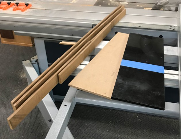
Photo 1 shows the few materials required to make the vacuum box. In making the jig, the main variable to consider is the position of the table stop underneath the in-feed end of the jig relative to the group of suction holes in the top plate.
To measure distance between the centre of the thicknesser cutter-block and the in-feed table edge, take a length of cheap softwood (such as pine) and screw a small block on one end of it. Place this on the table with the block snug up against the front edge, thus preventing any chance of it from being fed through the machine.

With the table lowered, switch the machine on, then slowly raise the table until you can just hear the cutter-block engage the wood. At this moment, lower the table and turn the machine off and remove the piece of wood. Now, measure between the block and the centre of the scallop that the cutter-block has created – this is where the suction holes are drilled in the top panel of the jig (photo 2).
The jig is only 200mm wide overall, allowing a thickness capacity of no more than 180mm (due to the absence of suction holes near the edges). For a wider jig a second vacuum extractor would need to be employed.
Now the outer dimensions of the jig must be calculated. Here the in-feed end is 368mm long, and the width is 200mm. The overall thickness will include the 35mm outer diameter (OD) of the vacuum hose that attaches into the in-feed end. Add to this enough on either side of the hole, and also the thicknesses of the top and bottom panels. In my case,
I wanted it at 70.5mm, leaving a little to clean up to precisely 70mm once the jig was complete. The length of the out-feed end of the jig is arbitrary, but I made it 232mm, making the overall length of the jig an easy 600mm.
Inside the jig
Strategically placed baffles and deflectors inside the jig allow a smooth sweep of airflow, while keeping the overall volume to a minimum. These parts also prop up the top panel, especially around the suction area where most downward pressure will be exerted.
I chose low-friction and rigid 10mm thick acetal* or Delrin for the top panel. Flex around the suction area is to be avoided for obvious reasons, so two baffles, one with a pair of 35mm holes, are placed close to the holes. The rear-facing baffle blocks off the back of the air box, where two 4mm holes are drilled, one in the top plate and one in the bottom act to equalise atmospheric pressures. A 45° gusset is fitted against its forward-facing face to avoid turbulence.

A pair of 12mm jarrah dowels further support this area without blocking off any suction holes. The front- facing part of the inside has a pair of deflectors that funnel airflow to the extraction port. Other props are fitted to spread the load (photo 3).
Prepare the top plate
The parts are shown above in fig.1. First cut the top acetal plate and 9mm MDF base to final dimensions – in my case 600mm x 200mm. Cut the other 9mm MDF parts parts to size and the correct angles.
The joints are all end-to-face ones that rely on no more than glue, and, on the sides, some fine nails as well. Nails should not be used anywhere else.
There are five lines of 4mm vacuum holes (43) that fit within an area measuring 176 x 48mm area calculated for optimum suction.
The distance between the last line of holes and the in-feed end of the jig is the measurement we got from the stick of pine, plus the desired width of the stop block (or hook) under the jig, less, say, 2mm. So, if the stick reveals 320mm, as is the case on my AD410 and the stop is 50mm wide, the last line of holes is 320 plus 50, minus 2 – equalling 368mm from the in-feed end of the top acetal panel. This makes for maximum suction at the moment the cutter-block first engages the veneer (the moment when things can go awry).

I used masking tape on the panel to mark the hole centres with a fine pen, centred them with an awl, through- drilled them on the drill press (photo 4) and then de-burred them.

Using cyanoacrylate (CA) glue, one end of each dowel was fitted to the inside face of the plate, so as not to block off any holes (photo 5). Position them carefully to even the load.
The inner parts
Three 35mm holes are drilled with a forstner bit – one in the in-feed end piece that the vacuum hose fits in to, and two in the piece in front of the suction hole area – round the edges of these two holes for freer air flow. Then, using a perfectly flat working surface, these internal MDF parts can be carefully assembled using a good PVA glue. Place nails where you can.

The bottom plate is then glued on to the frame just made. Using several weights (bottom facing up), no clamping is required as they invariably cause twist and shift. When this is ready, the 45° pine deflector can be glued in place, together with the remaining props (photo 6).
Gluing the top plate

Polyurethane is the only glue I know of that works well bonding acetal to other materials, and due to the gentle shear stresses involved in this application, I believe it to be fit for purpose. At this point do a dry run and do whatever fettling is required. Next, apply PU glue to the frame (photo 7) and position the top plate and weights.

For ease of calculating the veneer/ laminate thicknesses when thicknessing, I like the jig thickness to be a nice round number – in this case 70mm. Remember, I chose to make the jig 70.5mm thick, so that I could feed the entire box through the thicknesser at precisely 70mm – taken off the bottom MDF face only (photo 8).

Yes, I know – it’s very abrasive stuff (photo 9)! Lastly, glue the table stop to the bottom of the jig at the in-feed end, and now the jig is done.
Using the jig

There’s no rocket science to this, other than to remember the cutter-block will zero on the acetal face at a setting of 70mm, which means that if a veneer of 1mm is desired, the final pass will be set at 71mm (photo 10). And don’t forget to attach the vacuum hose to the jig and turn on the machine – yes, I didn't the first time, and with a pile of wood-shards as a result of my efforts, was about to bin the jig as a failure!
The jig is placed in the middle of the thicknesser table and pushed forward until the stop hits its edge. If there’s any concern that it may slide out from this position, you could attach a pair of ‘ears’ to the edges near the in-feed end and clamp it to the table.

Feed speed is set at its slowest, then a veneer placed on the jig under the cutter-block and the table slowly raised until the in-feed roller engages it and carries it through (photo 11). This is our starting point. Raise the table in 0.2mm increments per pass, and if necessary change grain direction if chatter is detected. For particularly difficult woods I may make only 0.1mm passes. However, it is worth noting that some highly figured woods simply will not cooperate, and can only be reduced through abrading.

This shop-made device has been a real godsend for making accurate, clean- as-a-whistle laminates or veneers that require very little finish-sanding (photo 12) – something that can’t be said for commercial or drum-sanded veneers.
* Acetal is a type of plastic that can also be worked with woodworking machinery and tools. It’s available at most plastics suppliers – the 10mm piece used here cost me $60.
Neil Erasmus is a designer maker, teacher and writer. See Instagram @neilerasmus