


After water, tea is the most popular drink in the world. Its consumption equals all other manufactured drinks, including alcohol and coffee put together. Back in 1907 an American tea merchant named Thomas Sullivan began distributing samples in small bags of chinese silk—the early beginnings of tea bags as we know them today. Not surprisingly tea boxes can provide a memorable and special gift, one that will endure as a family heirloom.
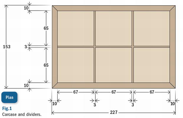
The dimensions of the box are based on the size of a 77 x 65mm Twinings tea bag and each of the six compartments can hold a pack of ten. The plan dimensions shown in fig.1 give a snug fit for 60 bags.
For this project I chose some silky oak which had been destined for someone’s fireplace. The lid came out of a fork and the sides out of another stump. The uniquely marked, contrasting wood grain will make a statement in any setting.
Accuracy is critical
Step one is to resaw, thickness plane and drum sand the carcase stock to 10mm and then thickness and joint one long edge. A thickness of 10mm provides a balanced look with enough glue surface at the mitred corners. If you are working with one long board, machining is straightforward.
If you are using two or three pieces of wood, as I did, it’s important to run each piece through successive thicknessing passes so they end up the same.
Accurate end cuts are critical for clean seamless mitres and squareness. Even small cutting errors translate into big joinery problems for boxmakers. Opposite sides must be cut exactly to the same length, with spot-on 45° mitre angles that are precisely at 90° to the long axis. The auxiliary fence jig described opposite will reward you with perfect joinery time and again.
At this stage you should have two sides each of 153mm length and a front and back each 227mm long—all pieces are 83mm wide and all marked to indicate the top (or bottom) and end joinery (photo 1).
Now is a good time to cut rabbets for the bottom panel (photo 2). Use your router table with a spiral up-cut or rabbeting bit set to 5mm high (half carcase thickness) with the fence set back to the thickness of your bottom piece (nominally 5mm). You only have to rabbet the top of a side, instead of the bottom, to painfully learn the importance of good mark-ups!
A piece of blue tape with a cross on the outside top face ensures I cut the inside bottom. A small pushstick keeps the workpiece flat over the cutterhead. You can use your free left hand to safely push the workpiece into the fence.

1. Carcase pieces thicknessed with end cuts and top and bottom marked so the grain travels around the box. Ripping to final width is next.

2. Blue masking tape with a cross shows which face and side not to rabbet when routing the base rebates. If working with one long piece rebate the whole length before crosscutting.
SETTING UP A MITRE SAW FOR ACCURATE CUTS AND PERFECT BOX JOINERY
Even minute errors on mitred corners will make the difference between nice joinery and something you are less than proud of. I’ve learnt not to trust defaults on any compound saw and not to rely on freehand cutting to mark up lines for repetitive machining. An auxiliary fence (jig) (photo A) which positions and clamps the workpiece solves most problems. Saw tune up solves the rest.
Build an auxiliary fence using 16 or 18mm MDF. This fence is sized for my 10” chop saw; it’s 100mm high, 120mm deep and 610mm wide, glued and screwed square. It secures to the aluminium saw fence with countersunk bolts and wing nuts. The fence height is sized to act as a depth stop, which beats chopping right through the base!
On the left of the fence is T-track which secures a sliding stop. The base is drilled with 20mm holes to position a Festool MFT SP clamp.
The primary purpose of the fence is to hold the workpiece firmly and eliminate any vertical cutting creep. This is almost impossible to achieve on small components without clamping, at least with any degree of safety. You may not notice it, but inevitably the error is there. The second function is to enable spot-on repetitive cuts, such as carcase sides of equal lengths.
Now it’s time to tune the saw. You only need to do this occasionally, but I check for each project. Remove the sliding stop block, and position the saw at 45°. Chop a largish piece of scrap (about 50mm square). Use your compound square to check for an accurate 45°. If it’s off, scrub the detente position and manually adjust until it’s perfect. (You will need to fix this sooner or later as it means your 90° cuts are also out.)
Now for the sneakiest and most common error, cuts that are not truly vertical i.e. 90° to the long axis. Rip some 16mm melamine chipboard to about 80mm wide. Use a square to mark some set up lines near one end of one face. Position a set up line a whisker to the left of the fence cut line, secure with a Festool or toggle push clamp.
Then chop (photo B). Do not be surprised, if you have a compound saw, to find the cut is not truly parallel to the set up line. Even a whisker out is not good enough for small boxes.
The fix is simple. Back off the blade head’s tilt lock screw a little, tilt the blade fractionally to the right, and use a crescent wrench to adjust the tilt stop upwards in tiny incremental steps, testing with repetitive cuts on your set up lines. When you nail it, lock it all up. I found that my digital angle gauge could not achieve this degree of accuracy.
Now you’re ready for truly accurate cuts. With four overlength pieces you don’t need the sliding stop for the first set of cuts, just line up your pencilled cut mark to the left of the fence kerf line. But ensure you use it for the second set of cuts when targeting perfectly matching component lengths (photo C).


B. Test set up piece secured with C. Sliding stop in use for repeatable accuracy.
Festool clamp.
NO CLAMPS, NO HASSLES
We are now ready to approach glue-up. Sand the the inside faces to 220 grit, place masking tape along the inside edge of the mitred corners, flip to face up and align the marked ends for chosen endgrain orientation.
I have tried many different ways of clamping small mitred boxes, always with some apprehension. But that’s all behind me. Clear packaging tape does the job quickly and fuss free. And, you can look forward to perfectly seamless joinery (photos 3, 4, 5).

3. Push the ends of matching pieces together and take care with bottom and top alignment. Secure with a short length of tape along the top edge. Then run a second piece overlapping this flush to the bottom. You shouldn’t see any gaps. Repeat for the remaining two joins. The carcase is laid out, taped and ready to fold into a box. Do a dry fold to ensure you have it right and then apply generous glue to each mitred edge.

4. Glue-up doesn’t get any easier than this. Snug the last corner together and secure with tape. The joints are already looking pretty good but to pull them tighter, run more packaging tape continuously around the box (pulling the tape firm on corners). Two layers should do it. And there’s a bonus! The clear tape ensures that excess glue squeezes inwards onto the inside corner masking tape. Peel the masking tape (not the outside tape) just as the glue is going rubbery.

5. Check for square by measuring the diagonals. Use a small stick with a brad through one end. Push the brad into one corner and mark the opposite inside corner on the side of the stick. (No sighting, positioning or memory errors!) Then place the stick across the other diagonals. If the measurement is the same, and it probably is if you paid attention to the cutting, you have nailed it! If one diagonal is a little longer, apply pressure across it and recheck. Your story stick will help you keep track of corrections.
LITTLE BITS ARE THE KEY
Mitred corners are inherently weak endgrain joints. A well fitted glued base and mitre keys strengthen the structure and the keys add a decorative element.
Solid wood bases move with the seasons so they are dodgy to use. Plywood looks cheap. The answer is to sandwich 3mm MDF with 1mm veneer on both sides (I used myrtle). After the veneer sets, trim the base oversize to 220 x 145mm and then nibble cut it on your tablesaw for a precise fit. Sand the inside of your base to 220 grit, then mask it and the inside carcase, to protect against glue squeeze-out (photo 6). Run a fine bead of glue around the inside perimeter of each and fit.
 6. Masking tape keeps difficult inside areas clean when gluing the base.
Mitre keys give structural support but what I enjoy most about them is how you can vary the number, length and angle to achieve different visual effects. I opted for three keys, each of different lengths grouped closely toward the top of the box.
First pencil the look you want onto one corner. Transfer these marks to a piece of scrap. Photo 7 shows how to set your box mitre key jig (see opposite). Tablesaw blade height determines the length of key and fence position determines its distance from the box top. Use a fine kerf blade for an elegant look.

7. Hold the jig and box tightly to the fence throughout the cuts for consistent kerfs and well fitting keys. Remove the set-up block before you start.
When your test cuts are right make a cut at each carcase corner, rotating the box through four successive cuts.
Repeat this process for the next two keys after resetting blade height and fence position.
Select wood for your keys, mill to thickness and rip to a width just wider than your deepest key slot (see my story in AWR#63 on making trivets for more on mitre keys). You are targeting a snug but not tight fit. Trim to oversize length and glue, firmly seating each key into the back of each slot (photo 8). After an hour you can trim to about 1mm proud with a dozuki handsaw. Flushing to the carcase sides with a stationary belt sander works well with care, but a sharp chisel and hand sanding works too.

8. It’s important to seat keys right back into their slots. Long keys like these run across the inside corners and need trimming with a chisel.
BOX MITRE KEY JIG
Mitre keys can be cut by hand but a tablesaw jig which runs along the fence will do the job neater and quicker. Build a solid jig. As you can see, mine has had plenty of use since I built it five years ago, and I never expect to have to build another one. Here’s a deceptively simple construction process.
All components are from 18mm MDF. Rip the sides to around 130mm, crosscut to 310mm length. Rip the cradle support stock to around 150mm width and crosscut to two lengths of around 200mm with a 45° mitre at one end of each piece.
Butt join the two mitred cradle piece ends at 90° with instant assembly glue (I use two-pack Mitre-Pro). Squeeze a modest amount of adhesive onto one face, spray activator onto the other, and bring together using a 90° angle for guidance. Hold for 30 seconds and the bond is good. Do not be tempted to nail or screw if you value your tablesaw blades!
Now centre the side of the cradle against one jig side. The base of the cradle sits flush to the base of the side. Use a combination mitre square to set one of the faces 45° to the side. Mark it up with a pencil, apply Mitre-Pro adhesive to the cradle side, spray activator onto the marked up jig side.
Bring the two faces together for 30 seconds. You have 10–15 seconds to wiggle things into place before the glue goes off. Flip the assembly so it sits flat on a table. Apply Mitre-Pro to the other cradle side and inside jig face and bring together, keeping them level on the table. Flip the jig on its side and flush up the top by ripping it through the tablesaw with its bottom against the saw fence. Flip again and reposition the saw fence so you can rip off most of the cradle bottom.
This minimises sawblade height and flex in use. Again you’ll need two passes, flipping end-to-end in between.
Final size is around 100mm high x 310mm long. Reinforce the structure with (PVA) glue rub sticks and screws through the jig sides (keep metal fasteners well away from tablesaw cutting area). I have found my jig easier and easier to use as the cutting area erodes because I can visually sight the blade against set up marks.
The jig can be used for angled mitre keys by simply tilting the tablesaw blade to the desired angle.
BREADBOARD LID
Tea boxes are rather utilitarian items and I feel that the design should reflect this—they are not jewellery or keepsake boxes—and shouldn’t look like them.
A hinged flat solid lid provides an appropriate look and helps keep the box height down. A one piece lid looks good, but has the potential for bowing as the grain tries to straighten with changes in humidity. Contrasting breadboard ends which run across the grain and are joined with splines, essentially eliminate the problem and provide a decorative element.
The lid overhangs the carcase sides by 2.5mm to create a shadow line, which is also a little less formal, in keeping with our design objectives. The bull-nosed front overhangs by 5mm.
This provides an overall lid dimension of 232 x 158mm. Deduct 34mm for the two 17mm wide breadboard ends and we require a centre piece 198 x 158mm. I had an oversize piece already re-sawn from another project so I simply had to thickness it to 10mm on a drum sander and semi-finish sand with 180 grit using a fine 2mm orbit sander.
The next step was to rip this centre piece to about 10mm oversize depth (168mm) and crosscut to exact width (202mm) in readiness for beefwood breadboard ends. The beefwood stock was thicknessed to 10mm, but otherwise left unsized, at this stage.

Step 1: This is my router set up for grooving the lid sides to fit a spline, with which we attach the beefwood strips. The lid has been marked with groove extremities and the fence stop blocks set to limit side to side cutting travel to 10mm from the front and back of the lid. Depth of groove is 7mm, both for the lid and breadboard ends.

Step 2: A similar set up applies to the breadboard end stock. However it has not been cut to width or length in the interests of ease and safety. Once again the outside face is against the fence in the interests of perfect alignment. Having made one groove, rip the piece off at 15mm and repeat for the other strip. Crosscut each piece to oversize lid length (about 190mm) centring on the grooves.

Step 3: A piece of scrap stock is thicknessed to 3mm, ripped to 12mm wide and crosscut to 136mm length to provide a hidden loose tenon, or spline. The groove, spline and workpiece faces are glued as you would for a biscuit joint. Bring all together with light clamping pressure ensuring all surfaces remain flat. Clean up glue squeeze-out immediately.

Step 4: Now this is a pretty smart flush cutting trick taught to me by a retired furniture maker. We have a centre piece with two ‘wings’ which makes ripping a bit hard. Insert a small piece of protruding scrap between the front wings. Set the saw fence so you can cut through the wings and back line of the lid. Now reset your fence to the required lid depth, test cutting on scrap. Turn the lid around so that the flushed back can ride along the fence and rip to final lid depth. Very cool!
Use a small cove cutter to round the front edges (be careful, back up the cut with scrap) and preliminary finish sand the front, back and sides with 220 grit, paying particular attention to retaining nice sharp side and back edges.
DIVIDING IT ALL UP
A snugly fitted box requires accurately positioned nesting dividers. Here’s a simple approach that uses half lap interlocking joints for great looking results.
I use my router table with a stock feeding sled and stops. A 3mm bit is used to cut the slots. Use this set up to slot a piece of 6mm scrap—this becomes a thicknessing gauge for the next step. (You could use a mitre gauge with sacrificial fence, or a tablesaw).
Rip and resaw an oversize selected piece of timber (I used myrtle to match the base) that’s long enough for the three dividers.
Then thickness on your planer and or drum sander using a sled. When you get close to 3mm thickness start checking with the slotted gauge (photo 9) until you achieve a snug fit. Rip to exact width (76mm) and crosscut to achieve the three dividers. Once again strive for an exact internal box fit. The two shorter dividers are slotted flat on the router table at dead centre and to 42mm depth. Use a stop to prevent the workpiece being pulled into the cutter (photo 10).
Slots for the longer divider are each the same distance from the workpiece sides so you can set the stop once and flip the workpiece for the second cut. But do check the cutting measurement against the plan as it’s easy to get confused on this one (if your internal box width is 207mm, the slots are centred on 68.5mm from the side). Get it right and the three pieces will all firmly nest square (photo 11) and snug into the box carcase with each of the cavities sharing the exact same width i.e. a whisker over tea bag width.
HINGE CHOICE
Hinge choice is important both to design and function. Traditional butt hinges look odd on a flat one-piece lid and may not provide the long term stability required for frequent usage. Full width piano hinges look crass and compromise the finely handworked presentation of the box. I used two 50 x 8mm round cornered hinges which are both fine and stable.
THE END GAME
I used small feet (27 x 27 x 5mm) to lift the box and create a shadow line. (Mitre-Pro works well here). A small ball chain secures an open lid. Dismantle the box and start sanding. This doesn’t take long as we have been sanding with 180 grit at each step. I use a combination of hand sanding with a block and my 2mm orbit small base flat sander. Work up from 180, 220 to 320 grit. Dust off between grits. Then rub briskly with 0000 extra fine steel wool. This works so well you will want to stop right here!
I usually use two or three diluted shellac coats on the inside of a box and rub with steel wool. After masking off the inside with tissues and tape, I sprayed the outside carcase and both lid sides with two coats of Mirotone’s Mirocat 3242, a pre-catalysed sealer, wet on wet. After 90 minutes a light hand sand with 320 grit followed by a rub with 0000 steel wool and the hard work is done. (You could use a few coats of shellac and rub back with steel wool—it doesn’t fill pores as well and provides less protection to abuse, but looks pretty much the same.)
Finally, I remove the internal masking and rub Mirotone Mirowax onto to all surfaces and allow 24 hours for drying. A brisk hand buffing followed by reassembly is next.This very easy finishing process provides a beautiful soft sheen and silky smooth surface which is surprisingly durable.


Geoff Birtles
Note: These are set up photos. All tools, and the workpiece, are removed prior to switching machines on.