Maloof Style Rocker

Words and photos: David Dundas
Rocking chairs in the elegant style pioneered and developed by Sam Maloof have acquired a formidable reputation for requiring their makers to possess exceptional skills. They are generally regarded as being beyond the scope of the average experienced home woodworker. However by substituting an upholstered slip seat for the classic sculpted solid-wood seat, and by using mortise-and-tenon joints only for the rail joinery, I have designed a chair which is both comfortable to sit in and not too difficult to build.

Photo 1
The mortise and tenon joints must be accurate, so these should be cut with well-made jigs. To align the holes for the dowels used to join the arms to the legs, and the legs to the rockers, I used a simple shop-made jig (photo 1) and a router with a guide bushing. Dry-assembly and metal dowel centres were used to determine the exact positions for some of the dowel holes.
Each member of the back-leg, front-leg, arm and side-rail pairs is a mirror image of its twin. It is vital to keep this in mind when marking out the joints, otherwise you may find you have made two identical right- or left-hand parts instead.
Construction
The side assemblies, consisting of a back leg, side rail, front leg, arm and rocker, are first glued up. The front rail and back assembly (top and bottom back rails and back slats) are then glued between the side assemblies. The chair is reinforced with blocks glued and screwed to the rails to support the upholstered slip seat. Before gluing up, the parts must be shaped as much as possible.
To prevent the possibility of delamination, it is essential to use urea-formaldehyde glue for the bent laminations of the back slats and rockers. Because the glue ups are fairly complex and time consuming, a slow-setting glue is required. I used super-strength epoxy for all the joints.

Making the Back Legs
Make a template for the profile of the back legs (fig.1). Trace this onto planed stock and bandsaw the two back legs, cutting the bottom of each leg 25mm longer than the profile to allow for later trimming to final length. Plane the flat for the side-rail mortise to the marked line, ensuring it is square to the faces. Use planes, rasps and sandpaper to fair the back and front of the legs to the marked line, but do not round them over at this stage.
After routing the mortises in each back leg, bandsaw and shape the inner profile. Roughly round over all the edges of the back legs, except near the joints. The final shaping of the joints must be left until the side and back rails have been made. Gouge away the corner between the side-rail and bottom back-rail mortises to provide clearance for the back corners of the slip seat.
Front Legs and Rails
Prepare the stock for the arms, rails and front legs, cutting the back ends of the arms, the front ends of the side rails, and both ends of the front and back rails at 85º (figs 2, 9). Mark out the mortises on the back legs and side rails (figs 3, 8), and the tenons on the rails (figs 4, 8, 9), making sure the back legs and side rails are mirror images of one another. Use a mortising jig to rout the mortises in the marked positions.

Photo 2
Cut the tenon shoulders using a mitre gauge on the tablesaw. For the shoulders of the back and front rail tenons, the sawblade is set vertical and the mitre gauge is angled at 85º (photo 2). The shoulders of the side-rail tenons are cut with the sawblade tilted 5º from the vertical and raised just 6mm, and with the mitre gauge set at 90º.

Photo 3
Cut the cheeks of the tenons on the back and front rails with a tablesaw tenoning jig, or with a router jig. To cut the compound angled tenons on the side rails, I used a pair of 5º wedges attached to the tenoning jig with double-sided tape to tilt and twist the workpiece (photo 3). When the tenons have all been trimmed and fitted to their mortises, dry-assemble the back and side rails to the back legs, and the front rail between the side rails to ensure the fit is correct.
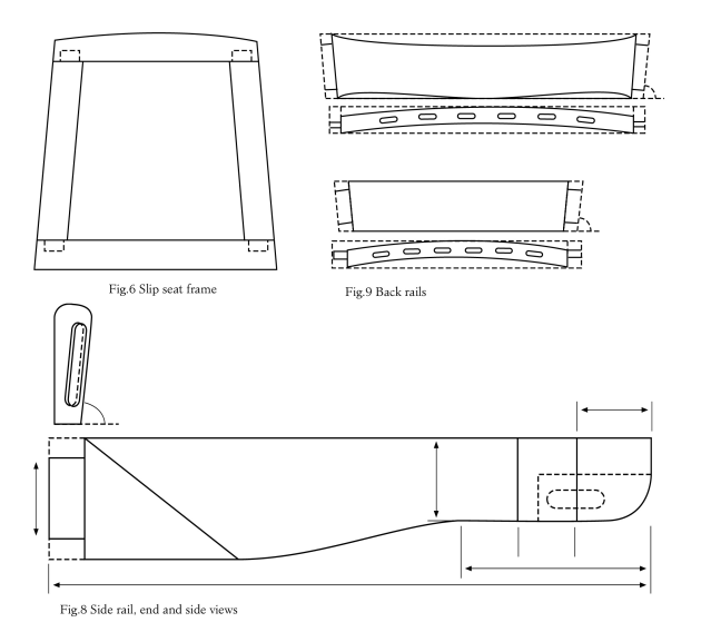
The front leg and side rail meet at a lapped joint. Cut the housings for the front legs on the outer faces of the side rails (figs 2, 4, 8), before bandsawing and shaping the curved profile of their bottom edge; plane the facet on each of their outer faces (fig 8), and round over their top edges. Round over the lower edge of the front rail to match the side rails.
The Front Leg Joints

Photo 4
Mark out and cut the housings in the front legs and make sure they fit snugly into the housings in the side rails (fig.5). Drill a pilot hole through the side rail and into the front leg for a screw to reinforce the housing joint. Mark the dowel positions on the top and bottom of the legs and use a dowelling jig to drill the holes (I used my jig with a router). Mark out and bandsaw the profiles of the inner, outer, and front faces of the front legs. Fair the faces of the legs with planes, scrapers and sandpaper, and round over their corners.
Making the Rockers and Back-Slats

Photo 5
I used hardwood stock for the back slat and rocker formers (photo 5). Mark and bandsaw the curves. Smooth the curves and line their faces with packaging tape to prevent glue from sticking to them. Cut the stock for the laminae about 125mm longer than the finished length (so that snipe can be docked from the ends) and joint its edges square. Rip off the laminae about 2mm thicker than their finished thickness and machine them to 4mm and 6mm.
Use a rubber roller to apply the urea-formaldehyde glue to a pair of back slat laminae, and clamp each pair in the former and allow to cure for eight hours. Apply the glue to all six laminae for each rocker and clamp them in their former in a similar way.
Make sure that all the laminae are properly aligned and level with one another in the former. I planed the laminated back slats to their final width and rounded over their edges on the router table with a 5mm radius roundover bit. The laminated rockers were planed to a final width of 35mm.
Rocker blocks are glued on the rockers where they meet the legs. Make these either from a single thickness of wood, or laminate contrasting woods for decorative effect. Mark on the top of the rockers the positions for the blocks, which are centred 90mm and 560mm from the front ends. Shape the bottom faces of the blocks to match the curve of the top of the rockers by planing and then rubbing the block against a strip of sandpaper attached with double-sided tape to the top of the rocker. When the curves match, glue the blocks in place. Leave the rounding over and fairing of the rockers until the dowel holes have been drilled.
Making the Arms
Bandsaw away the waste from the inner and outer faces, the top and from the front end of each arm, but leave the underside until the position of its dowel joint has been established. Drill the dowel hole in the rear face of the arm which has been docked at 85º to its inside face, using a dowelling jig, and then lay aside the arms until the other dowel joints of each side-assembly have been made.
Making the Dowel Joints
I made a dowelling jig from 9mm MDF or you could use acrylic sheet. The jig is screwed in position with 4-gauge screws to rout the dowel holes, using a 5/8" guide bushing and a 1/2" solid carbide spiral-upcut bit. The jig ensures that the dowel holes are properly aligned exactly perpendicular to the plane of the joint. Since the planes of most of the chair joints are not perpendicular to adjacent faces, regular doweling jigs cannot be used to align the dowel holes.
On each side of the chair, four of the dowel holes, which are in pre-determined positions—at the top and bottom of the front leg, at the back end of the arm, and in the centre of the front rocker block—can now be routed with the jig. Once the bottoms of the back legs have been trimmed to length, and the dowel holes have been routed in them, the positions of the remaining three holes—on the rear rocker block, the flat for the arm on the back leg, and the underside of the arm—are determined, in that order, by using metal dowel centres in the matching dowel holes, and dry-assembling each side-assembly in successive steps.
Dry-Assembling the Sides
The first dry assembly is needed in order to establish the exact length of the bottom end of the back leg. Clamp the side rail onto the back leg, and insert a dowel in the front rocker block; place the front leg onto the dowel and clamp the housing joint with the side rail. Next, pivot the assembly on the dowel and mark the position of the cut on the bottom of the back leg. Disassemble, and make the cut on the sliding compound mitre saw, with the back leg resting on its outer face and the side-rail flat clamped against the fence; I found the saw table needed to be angled at 18º and the blade tilted 5º from vertical.
The angling and tilting will be in opposite directions for the two back legs, and you need to take care to ensure you have made the appropriate setting for each leg. You also need to check that the distance from the side-rail mortise to the bottom of the leg is the same on each leg, otherwise the chair will be lop-sided. It is best to creep up on the final length of the leg, and to dry-assemble several times until you achieve a snug fit of the bottom end of the back leg to the rear rocker block.
You can now rout the dowel hole in the bottom of the back leg. Establish the position of the rear rocker block’s dowel hole by dry-assembling again and placing a dowel centre in the hole in the back leg. Rout the hole at the marked position and fit a dowel.
Dry-assemble the side-assembly again, clamp the joints, and clamp the assembly upright in a vice. Lay the arm flat on top of the front leg, and test the fit of the rear end of the arm against the back leg. The flat on the back leg will need to be planed with a block plane to make it parallel to the rear face of the arm.
When you are satisfied with the fit of the joint, place a dowel centre in the dowel hole in the arm and mark the dowel position on the back-leg flat. Rout the hole and fit the dowel. Finally, place a dowel centre in the top of the front leg, and mark the dowel position on the underside of the arm. Rout the dowel hole and fit the dowel to complete the dry-assembly of the side assembly.
The outline of the top of the front leg can now be marked on the underside of the arm, the waste bandsawn away, and the arm carved. Similarly, the outlines of the legs are marked on the rocker blocks and the waste similarly removed.
Back Rails and Assembly
On the top face of each rail, mark out the curves defining the front and back faces (fig.9). These curves are arcs of circles 1270mm in radius for the bottom rail and 1860mm in radius for the top rail. Bandsaw the front-face curves and smooth the faces with a compass plane or scraper, followed by sanding. Retain the curved offcut from the front face. Part of the offcut can be cut off and faired to use as a curved fence to be attached to the router’s edge-guide for routing the back-slat mortises. The remainder is used as a caul for clamping the rail in a vice.

Photo 6
Mark out and rout the back-slat mortises on the back rails (see the cutting list for mortise parameters), using a router edge-guide with a curved fence attached (photo 4). Bandsaw the curved top and bottom edges of the top rail. Finally, bandsaw and smooth the back faces of the rails, and round over and fair their edges.

Photo 7
Pare the bottom ends of the back-slats and mark them, so that they fit snugly in their individual mortises. Dry-
assemble the back rails between the back legs; insert the back-slats into the bottom back-rail mortises, and mark their top ends for trimming to final length. Disassemble, fit the slats and re-assemble (photo 6). Check the measurement between the tops of the tenons on each side, and dry-assemble the back assembly between the back legs.

Photo 8
Complete as much shaping and sanding as possible before gluing up and clamping each side assembly in turn using super-strength epoxy (photo 7). When the glue is cured, complete the final fairing and sanding of the joints before gluing the back assembly between the two side assemblies, using 5º wedges for clamping.
Seat Frame
Make the glue blocks (fig.2), and glue and screw them to the rails to reinforce the chair and provide support for the slip seat. Finally make the slip-seat frame (fig.6) from secondary hardwood, leaving a gap of 3mm all around to provide clearance for the upholstery. I had the seat professionally upholstered, using elastic webbing supporting a layer of foam covered by leather.

Photo 9
Polishing
Fit the finished seat but remove it before polishing the chair with your preferred finish. Once you have refitted the seat you should now have a piece which is guaranteed to be either your own or someone else’s treasured family heirloom.

Photo 10
Cutting List (length x width x thickness)
Back legs (2) 2000 x 200 x 46mm Allow 25mm at the bottom of the legs for trimming to final size. For the mortise parameters, see the corresponding tenons.
Front legs (2) 510 x 45 x 45mm
Front rail (1) 530 x 90 x 34mm Allow for 16 x 45 x 12.7mm tenons, shoulders are 495mm apart at front edge.
Side rails 2 476 x 90 x 30mm Allow for 25 x 60 x 9.5mm tenons.
Arms 2 454 x 70 x 45mm
Bottom back rail (1) 437 x 90 x 46mm Allow for 25 x 60 x 12.7mm thick tenons, back slat mortises are 29mm wide x 8mm thick x 13mm deep and 25mm apart. Curve is 1270mm radius arc.
Top back rail 1 580 x 115 x 46mm Shoulder to shoulder at top 538mm, tenons 20 x 80 x 9.5mm, back slat mortises are 29mm wide, 8mmm thick, 25mm deep and 35mm apart. Curve is 1860mm radius.
Back glue blocks (2) 160 x 45 x 45mm
Front glue blocks (2) 120 x 65 x 34mm
Back slat laminae (12) 760 x 34 x 4mm
Rocker laminae (12) 1220 x 42 x 6mm
Rocker blocks (4) 140 x 40 x 25mm
Slip seat back rail (1) 416 x 60 x 16mm Add 3mm for planing to fit.
Slip seat front rail (1) 489 x 60 x 16mm
Slip seat side rails (2) 400 x 60 x 16mm Allow for 19 x 38 x 6.3mm tenons.
Rocker former (1) 1200 x 200 x 45mm
Back slat former (1) 750 x 175 x 38mm
First published in Australian Wood Review, issue 40