Making the Compass Clock
Words and photos: Andrew Potocnik
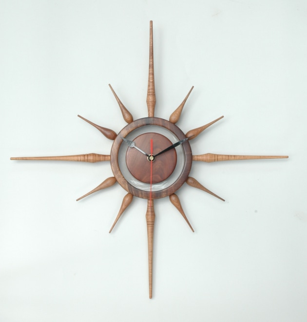
Over the years I’ve acquired all the parts for making a clock, but never got around to designing and making one. Earlier this year, after doing a few rough sketches, I settled on a compass-like layout, except the N, S, E and W indicators would represent the quadrants of a clock. The central hub had to be big enough to enclose the mechanism and the surrounding ring had to be thick enough to house the spindles.
Turning the hub
I began by gluing a block of gidgee with hot-melt glue to a sacrificial blank of redgum gripped in my old engineers three-jaw chuck. You could use PVA or another adhesive, providing you have ample contact surface and allow time for glue to harden.

1. I used the tail-stock centre to locate the block and clamp it in place while glue hardened, before truing it down and filling any cracks and voids with superglue. Be sure to keep knuckles clear of the jaws as they spin past almost invisibly. Once dry, the hub was trimmed to size, and sanded through to 320 grit. The centre of the hub was located with a V-shaped scraper, so a centre hole for the clock mechanism could be drilled. I used a scroll chuck in the tailstock, and an 8mm diameter drill bit to bore a hole through the hub later so it could be reversed and hollowed to accept the clock mechanism.

2. I faced the jaws of my chuck with thick PVC electrician’s tape to prevent marking and compression of fibres in the hub, but still allow ample grip for the next stage for which I used a Forstner style bit to determine the diameter of the opening I needed to hollow.

3. My key concern here was how much wood to leave inside the hub so the stem of the clock mechanism would protrude sufficiently for this project to work. To determine this I used a vernier caliper, leaving a cavity large enough to house the clock mechanism and enough wood to fit a cover later.
Outer ring
Although a well thought-out project is planned well in advance, this one developed from an overall idea with components finalised as work progressed. A blank of blackwood was glued to a carrier, trimmed to size, sanded and parted to about 19mm width allowing the exposed interior to be fine turned and sanded through to a final surface.
Cardinal points

4. Some fiddleback blackwood was turned down to an 18 mm diameter, checked with vernier calipers...

5...before a 8mm tenon was cut with a parting tool...

6....and an overall profile shaped and sanded.

7. A pair of detail lines was neatly cut with a skew chisel to break the overall profile of the form. Using two fingers wrapped around the underside of the toolrest to support the thin spindle and prevent chatter, a clean V was cut using the long point of the skew.

8. I could now determine how broad the outer ring needed to be to correctly house the hub and parted most of the way through it.

9. This was divided into 12 segments using the indexing scale in the lathe’s stepped pulley. I then divided the breadth in half to locate where holes would be drilled to allow attachment of the hour indicators.

10. Sawn free, the ring was transferred to a jig that enabled accurate drilling of holes to accept the 8mm tenons.
Decision time — what shape and size to make the smaller hour markers?

11. I settled on 80mm long elongated teardrop-shaped forms, so back to the lathe to make eight that were near enough to identical.

12. Once completed, I arranged them in line to compare them.

13. These and all the other parts were pre-finished before a trial fitting of indicators showed whether their proportions and shapes would work out.
Fitting the mechanism

14. The outer ring was fitted to a jam fit carrier, in this case a piece of western red cedar attached to a faceplate, so the back could be trimmed down, sanded and a recess cut to accept a perspex ring that would hold the hub and ring in place without any unsightly braces.

15. The 3mm plus recess was cut with a granny tooth scraper.

16. Next the hub was remounted to a stepped carrier fitted to my three-jaw chuck. This allowed me to cut a step, onto which the inner portion of the perspex could be glued.

17. My tailstock centre helped hold the hub in place so that no glue was used at this stage.

18. For the perspex spacer a carrier of MDF was screwed to a faceplate and numerous small pieces of thin double-sided tape attached to the carrier, so the perspex could be held in place and cut to size with a parting tool.

19. Vernier calipers were used to ensure dimensions were accurate...

20. before the centre section was parted free...

21...for a neat fit.

22. Projects should look good from all angles, so a cover for the back was made. A disc of figured blackwood was gripped in my three-jaw chuck, turned to size and a step cut with the granny tooth scraper to create a step that would fit precisely inside the recess cut into the hub earlier.

23. Another carrier was turned so the outer surface of the cover could be shaped and sanded, before fitting to the hub.

24. With all components completed it was time to assemble the clock. At this stage I also made a stand so the clock could also be free-standing. As it turned out I didn’t win a prize, but I was still happy with the piece I had made.
First published in Australian Wood Review, issue 81.
Andrew Potocnik is a wood artist and regular contributor to Australian Wood Review who lives in Melbourne.