Making an Infill Shoulder Plane
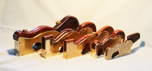
Above: A suite of shoulder planes made by Ian Wilkie.
Words and photos: Ian Wilkie
Diagram: Graham Sands
Although they may not be your first priority in woodworking tools, shoulder planes are very handy for traditional hand work. Nineteenth century infill shoulder planes were minor works of art, with bronze or steel bodies ‘stuffed’ with exotic woods, but they are relatively simple in construction and do not require any special skills to make. The combination of spectacular wood and brass can make a very attractive tool.
There are several ways to make the metal body, but perhaps the easiest way is to cut brass pieces from stock bar and rivet them together. This requires only basic tools and a little care to make a strong, neat plane body.
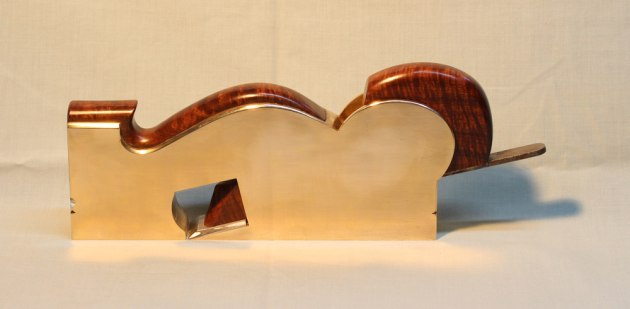
A 25mm brass shoulder plane with ringed gidgee infill.
The plane I will describe was fabricated from readily available, standard thicknesses of brass bar. Sides of 1/8" (3.2mm) thick, plus core- pieces of 1/2" (12.7mm) thickness, make a body 19mm (3/4") wide, which suits the 19mm Qiangsheng shoulder plane blade I used. The materials cost me around $55 ($30 for brass and $25 for the blade) and it took me all up 12 hours to make. I didn’t bother with a screw adjuster because they can be more bother than they are worth on this type of plane.
Setting is not difficult using a small hammer to tap the blade, and you rarely need to change it between sharpenings. The finished plane weighs just shy of a kilogram and has a nice heft.
The tools required include a hacksaw, a jewellers saw; a couple of flat files (one fine, and one coarse for the rougher work); a chainsaw file around 7 or 8mm diameter for smoothing inside curves; a small, extra-slim triangular file (or needle file) for the corners; some small G-clamps, and a medium sized (6–8oz) ball peen hammer.
A drill press is desirable, but not essential. The straight cutting, particularly of the thicker material, can be done with a 1mm cut-off wheel in an angle grinder, but do ensure the work is held securely before using any power tool.
Blade-bed angles for shoulder planes vary between 15 and 20°. I opted for 15° because it suited the bar stock I used, but 20° works just as well in my experience. The side profile is copied from an old G. Millers plane that appealed to me.
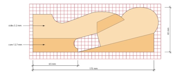
Fig.1 Brass body dimensions (scale to suit)
The dimensions are shown in fig.1, but there is no ‘standard’ shape for shoulder planes and you can choose whatever pleases you. If you use a different blade or side shape ensure the arch over the throat cut-out is deep enough to maintain body stiffness, and also allow for sufficient protrusion of the blade tang for adjustment. Note also that shoulder planes usually have a longer toe than regular bench planes (typically, more than a third, but less than half of the sole length). This helps to register it firmly on the work when starting the cut.
The shaded areas on the diagram represent the 1/2" thick core pieces through which the fixing rivets pass. The blade cannot be removed through a fine mouth, so allowance must be made for it to be twisted vertically and withdrawn through the wedge slot.
Parts for the body were cut from two pieces of brass; the core pieces from a 140mm length of 13 x 39mm (1/2 x 1-1/2") bar, and the sides from 350mm of 75 x 3.2mm (3 x 1/8"). Rivets were cut from 5/32" (~4mm) brass rod. Some makers prefer steel rivets, so if you like the contrast, bullet-head nails are soft and easy to peen, and make excellent rivets.
Saw, file and sand the shapes
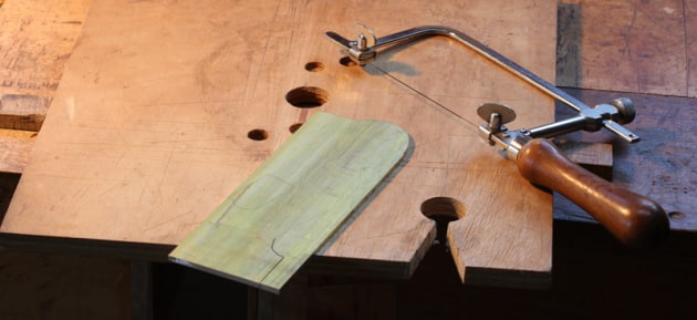
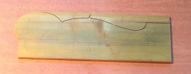
1. First stage in cutting out the sides.
Make accurate cardboard templates for your sides and core pieces, but before transferring to the brass, draw-file the edges that will form the bottom of the sole to get rid of the slight rounding that occurs on the edges of drawn bar. I cut out the shapes on a crude ‘bird-mouth’ clamped to the bench (photo 1).
A jewellers saw takes a little bit of time to master, but after a few broken blades you’ll get the hang of it. Set a steady rhythm, and try to cut close to your layout lines to minimise cleaning up, but don’t cut into your lines, especially along the sides of the blade bed.
2. Showing the saw cuts.
It required a few different approaches to reach far enough into the cuts with my saw, but I managed it by making multiple cuts as shown in photo 2. I couldn’t reach the top of the mouth opening from any direction, so I used a broken hacksaw blade with some cloth wrapped around it for a handle – crude, but it did the job.

3. Smoothing sides to layout lines.
Clamp the cut out sides together (photo 3), and file to the lines. File the edges of the small triangular bits that form the sides of the blade-bed straight, but leave the lines just visible for reference when assembling the body.
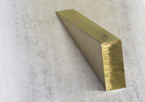
4. Squaring the core-piece for the blade bed.
The core pieces can be cut out with a hacksaw or a cut-off wheel. They need to be accurately squared up, and I find the best way to get them flat and square is to file close to the layout lines, then lap on some 180 grit paper stretched very tightly over a flat surface (photo 4). Check constantly with a try square and make any necessary corrections by leaning on the high side.

5. Parts prepared and ready to assemble.
After a couple of hours of cutting, filing, and sanding, the parts are ready to join (photo 5). Sand all mating surfaces smooth and clean. Leave the toe-piece square, it will be shaped to match the throat cut-out and form the mouth after assembly.
Mark, punch and drill rivet holes
Rivet spacing is not super critical, but you need to place them close enough to pull the sides tightly and evenly against the core pieces. I used six through the blade bed, five through the front piece and two for the wedge block (photo 10).
Mark out and centre punch the rivet hole positions on one side, then lightly clamp the sides to the blade bed and toe piece. Sit the clamped assembly on a solid, flat surface, and align the core pieces with the sides. Aim for minimal filing and cleaning up of
this area after assembly, so you won’t damage your nicely squared blade- bed. When all is shipshape, tighten the clamps firmly and drill the first rivet hole through the blade bed.

6. Crude but effective home-made countersinking tool.
Each side of the rivet hole needs a countersink, but don’t make these too deep, somewhere between a 0.5 to 1mm deep chamfer will do nicely. For this job, I use a tool I made from an old triangular file with the three faces ground at approximately 75° to form a sharp- edged point (photo 6). Four or five twists in brass are enough to produce an adequate, clean bevel – easy and safe.
Setting and peening the rivets

7. First two rivets in position.
After forming the countersinks on both sides, cut a rivet to length, allowing about 1.5mm protrusion each side. Don’t make them too long or you’ll have trouble hammering them down enough to fill the countersink bevel. Tap it into the hole, check that everything is still in position, then drill a second hole and place its rivet (photo 7). Do the same for the toe-piece.

8. All rivets placed and set.
If you’ve never set rivets before, practise by setting a few in some scrap pieces. File them flush and check that you have properly filled the bevels. Try prising the scraps apart when you’ve finished to see how well they hold. If you really mess a rivet up, don’t panic, they can be drilled out and done again.
Any lump of heavy, flat steel will do for a peening block. Hold the hammer close to the head and use light blows, hitting the rivet head with the ball not the flat face. The rivet will slide back and forth at first, so work alternately from each side until it locks in place with roughly equal protrusion on both sides.
Strike near the centre at first, going round in a small circle and gradually working the metal out to round it over and push it down into the countersink. If you mis-hit, light dings will sand out, but if you find you have lots of misses, a couple of layers of duct-tape around the rivets will provide some protection to the sides. Once you have a pair of rivets in each piece, the remainder can be drilled and set.
Fitting the wedge block
Now fit the wedge block. To ensure it ends up in the right place and at the right angle, I make a temporary wedge from scrap wood (don’t forget to allow for the blade thickness). Position and clamp the wedge block against this, and drill for its rivets.
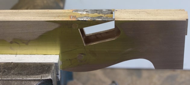
9. Projecting corners of sides soldered to blade-bed.
Photo 8 shows all rivets in place and hammered down. They don’t look very pretty at this stage, but that will soon change. To add some support to those thin projecting bits at the end of the blade bed, I silver-soldered them to the core, back to the first rivet (photo 9).
Cleaning up

10. Rivet heads filed and ready to sand flush.
To clean up the rivets, file off as much as you can without marking your sides (photo 10), then lap them smooth using sandpaper stretched over a flat, solid surface like a tablesaw top.
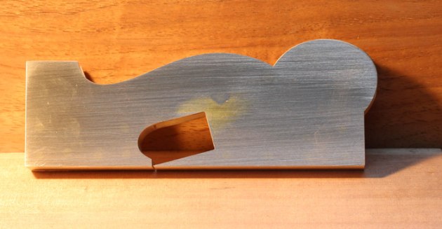
11. Side partially sanded, rivets disappearing.
Begin with 120 grit, and the rivet heads should start disappearing quite quickly (photo 11).
File any projecting bits of core flush and square with the sides, and clean up the throat and mouth. I tidied up the sides with fine files (round, flat, and triangular), using them as you would a spokeshave, holding the files straight across the edges and pushing them away in a straight line.
Take special care smoothing the sides to the blade-bed, this is the heart of your plane and it needs to be perfectly flat, and square to the sole if you want your plane to function well. All filed surfaces can be further refined with sandpaper wrapped around a small stick (or a bit of dowel for the inside curves).
Sanding to 1500 grit will give you a very nice matte finish, or you can buff it to a high shine if you wish. Add any detailing as you see fit – I used varying width chamfers and some ‘lambs-tongues’ to give my edges a bit of interest.
Timber infill and wedge

12. Fitting the infill.
Mulga was used for the infill and wedge, but any dense, dry wood should be suitable. I made a cardboard template off my drawing, cut it slightly oversize, then sanded and pared for a tight fit. Having the wood stand proud of the brass is traditional, so the visible edges were shaped and sanded (photo 12) before assembly. I then I glued it in place with epoxy, wiping off any squeeze-out with a rag soaked in methylated spirits.
The final steps are lapping the sole flat and square to the sides and opening the mouth. Don’t forget to have the blade in firmly (but not projecting) while you are lapping the sole, so the bed is tensioned as it will be in use.
Cut and file the mouth
A very fine mouth is desirable, so proceed very carefully with this step. I cut a small amount off (a bit more than a 1mm) the sharp end of the blade bed, then made a clean cut across the back of the toe-piece and checked if the blade would come through. It didn’t quite, so I used a very thin, flat file and filed a little at a time off the front of the mouth until the blade would project with a gap of around 0.25–0.5mm.

13. Test flight.
Take it slowly, because if you over cut the opening you cannot ‘fix’ it by using a thicker blade as you can with a bevel-up configuration. Don’t despair if it ends up a bit wide, the plane will still cut endgrain very well, but with a wide mouth, the edge of he blade is a bit more likely to catch on the corner at the start of a cut.
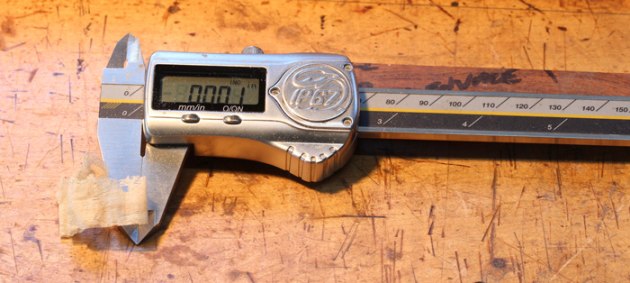
14. Full-width shaving, 0.01" thick.
Time for a test-run (photo 13). You may have to tweak the edge of the blade a little (mine was a degree or two off square as it came), but with a little fettling, your plane should be capable of taking full-width shavings of 0.025mm (0.01") (photo 14).
Finally, apply your favourite finish to the woodwork (I used Shellawax buffed with a cloth wheel), and the job is done...
Ian Wilkie is a Brisbane based woodworker and toolmaker who has written several stories for Australian Wood Review, see top right "related articles" on this page.