Making a fold-out step stool
Words and photos: Charles Mak
Diagrams: Graham Sands
I rarely work with published drawings. By matching an image of a finished build in my head, instead of following detailed plans, I have been able to free myself from a fixed path of work and allow myself to experiment with tools and techniques. Designed for everyday use and pleasure, this stool is another example of a project I completed using that approach.
Step stools are often your trusted helper for reaching hard-to-reach spots. Folding step stools made of polypropylene are therefore popular, and they are functional and economical. But – they have no personality. So, I was intrigued when my wife told me about a foldable two-tier step stool she recently came across. After hearing her out (including her desire for something similar but more elegant), I did my research and saw an opportunity to make a refined version of the ‘assembly required’ stool.
Redesigning the stool
My version preserves the two-tier and foldable design seen in a mass-produced copy. My wife wants the top to serve as a seat and not as a step, when the bottom step – to be used for quick up-and down-tasks – is folded up. I customised the dimensions to suit her purposes and also planned to include some embellishment in my version to add that touch of class.
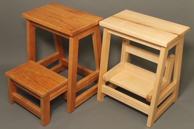
Tastes are subjective, but we can influence how people look at our work by making good decisions on, among other things, choice of timber, joinery, and details. The first change, therefore, was to use nicely grained wood to give the stool a warm and quality feel. Cherry and maple, shown in the image above, were chosen for this reason.
Well-executed joinery, even if it is hidden, is at the heart of of most of my work. I replaced the ‘screws and plugs’ assembly with floating tenon (domino) joinery. This change instantly removed the low-price item look of the original design. Of course, dowel joinery is also a viable option, so is the handcut mortise and tenon joint for the traditionalists.
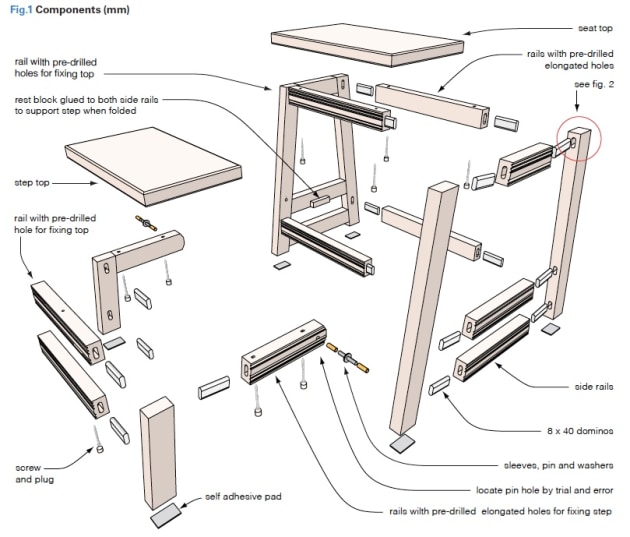
Finally, to transform a utilitarian object like this into an attractive piece, decorative details, especially those that carry a handcrafted feel, are essential. That was why I turned to a recent addition – a Veritas combination plane – instead of a router to embellish the moulding details. The result is a functional household accessory reborn with style and character (fig.1).
Getting the stock prepared
After acclimation, I milled all the parts on the tablesaw. Since the final dimensions of the step and its support were not worked out until after the main stool support was dry assembled, I cut the parts for the step and step support over length.
Hard maple is prone to burn marks during ripping. I ripped the maple in two passes, with the first pass a little proud. In the second pass, the saw shaved the wood as clean as a planer would. I then remove all the machine marks with a handplane.
Embellishing the rails
Adding decorative details with a plane is a good opportunity for you to put your hand skills on display.
I turned to my plough plane for beading, and the combination plane for reeding, dispensing with the need to change cutters.
To get the new blade ready, I put a finishing hone on the bevel face of the reeding cutter using a dowel wrapped with abrasive to gently hone the curve profile. Using a combination plane is no different from handling a plough plane.
Here are a few more suggestions that have served me well:
• First, choose straight grained stock for the mouldings to keep any tear-out concerns to a minimum.
• If you are new to using this type of joinery tool, start with a simpler profile (for example, a bead instead of a reed) to practise your cuts on a softer wood like pine. Try out the more complex cutters or on harder wood after you have gained your confidence.
• For complex profiles, set your cuts light, especially when working with harder wood, like maple, to have better control of your cuts. For reeding the maple, I set the depth of cut to about 0.25mm (photo 1).
• Lastly, wax the skates as well as the fence often, to reduce friction and binding.

1. Set the sliding skate in line with the outer quirk when using a reeding cutter.
The combination plane allows you to switch the fence to the other side of the body so you can cut from either side of the plane, to handle grain direction better (photo 2).

2. I switched the fence and my hand now and then to save overburdening my shoulder.

3. Labelling and marking helps when you have a lot of parts to deal with.
After cutting the reeds, I used the plough plane with a bead cutter to complete the moulding profile (photo 3). When doing handwork, remember slow, careful work without mistakes will get the job done faster.
Starting with the stool support
The stool support consists of the legs and the rails on four sides. The stool legs are angled for stability and the side rails are bevelled to match the angle. A mock-up – a tool often neglected by woodworkers – is a great way to work out configurations and details such as size, proportions, and mechanics in a three-dimensional manner. After trying a few mock-ups, I set the angle of the legs at 7°.

4. Mark the angled cuts clearly and use the marks to check with the blade or laser line before cutting.
With so many similar looking members, I labelled all the parts and marked out all the angled cuts on the stock as well, to avoid unnecessary cutting blunders (photos 3, 4). The angled legs and bevelled side rails were cut on the mitre saw (photos 5, 6).

5. A sliding bevel was used to verify the settings as the mitre angle gauge has identical vernier indices on either side of the 0° mark.

6. Use a stop block for consistency when cutting identical pieces.
Handling the joinery challenges
Achieving precision with the domino joinery in this project presented several challenges. For dead-on alignment the standard (smallest) mortise width setting is used, leaving no room for careless work.

7. If you struggle with mortising narrow workpieces, a trim stop will hold the rails in place for precise and repeatable mortise placement.
This requires accurate marking of all the lines and careful plunging of the cuts. Even a slight movement away from the pencil line when you plunge the machine would result in a misalignment of the mating pieces (photo 7).

Secondly, the top front and side rails are joined to the legs adjacent to each other and if the usual domino placements and plunge depths are used, one of the adjacent tenons would bottom out. My solution was to customise the plunge cuts so no adjacent tenons would hit each other (fig. 2).

8. Guide the layout with a tenon to prevent cutting the mortise all the way through the workpiece.
Thirdly, the side rails meet the legs at an angle of 7°. When laying out the mortise lines for those joints, use a tenon
to guide the marking to avoid the mistake of penetrating through the workpiece (photo 8).

9. Not interfering with the clamps, a flat body square was ideal for marking the square line on the rail.
To mark the mortise placement for the angled joint, clamp the rail and leg in position and draw a pencil line square to the leg (photo 9).

Lastly, although the legs are sloped, the front and back rails are joined to the legs perpendicular to the floor. To cut mortises for such arrangement, we turn to a technique using the milled flats as well as the scribed centrelines of the machine to position the domino joiner (photos 10, 11). This special technique is explained step by step in fig.3.

10. For narrow pieces, add boards to their sides to extend the intersecting lines and to increase the registration surface for the machine.

11. A hammer is a fine-tuning tool, used here to align the joiner with the intersecting lines.
Ending with the step support
The step support consists of the legs, two side rails, two front rails, and a mounting system to connect the step support to the stool legs. After dry-assembling the stool support, I made a template of the bottom step including the step, leg and side rail, and used it to determine the position of the hinge holes as well as the exact dimensions of the step support and the step leg. The parts for the bottom step were then cut to size based on this template (photos 12, 13).

12. A full-scale template made of cardboard easily finalised the step support set-up.

13. The final template was used to mark out the workpieces before cutting them to size.
The commercial version uses a long dowel to mount the step support to the stool legs. A round dowel here does not fit in with the whole build, made of all rectangular parts.

14. Does the idea hold up to a real life test? I stood on a scaled mock-up fabricated out of scrap materials to stress test the pin system.
Bolts could be used to mount the step support to the stool legs, but its use would likely give that ‘assembly required’ feel. After experimenting with a few ideas, I settled on a concealed pin system, made out of a few hardware supplies: a bolt cut to length, a pen tube to prevent wear on the wood and some washers 12 (photos 14, 15).

15. Nothing is more satisfying than finding your own solution to a taxing problem using simple materials.
In the final step before assembly, I did all the drilling, removed all the pencil marks, and broke the sharp edges. For the seat and step, I put a small round over to give them a softer, smoother look. Furthermore, rounding those edges makes them more durable against dents and splinters (photo 16).

16. To prevent blow-out, rout the ends before the sides.
Assembling and finishing
The usual assembly advice applies here: Dry fit, dry fit and dry fit. In addition, I broke down the assembly into phases, starting with gluing up of the sides first, which are composed of the legs and the side rails (photo 17).

17. Reduce glue-up stress by breaking down a complex assembly into sub- assemblies.
The pins were also glued to the predrilled holes on the stool’s front legs and the sleeves glued to the step legs, with a drop of oil added to the inside of the tube. After the subassemblies were cured, I assembled the front and back rails as well as the step support to the stool’s front legs at the same time.

18. To mark the holes for predrilling, clamp the step or seat in position and make an indentaton with a screw. Cover plugs can then be fitted.
It would be easier to apply the finish to the assembly before the seat and step were installed. So, I put a few coats of polyurethane to highlight the raw beauty of the wood grain with light sanding between coats, and then attached the seat and step. To cover the screw holes, I microwaved the plugs for 30 seconds or so and drove them home – with ease (photo 18). Mission proudly accomplished!
After all the stools I have built in recent years, I still have one stool that I have been wanting to do, one that is to be made based on measured drawings (from a book): Tage Frid’s iconic Three-Legged Stool. Sometimes, you just crave a classic. And, I am confident that Frid would have approved of my plan to build his three-legger where function meets beauty, and put it with one of my two- steppers under the same roof!
Charles Mak enjoys writing articles, authoring tricks of the trade, teaching workshops, and woodworking in his shop. Charles has just published a collecton of his tips and techniques: Woodworking Tips and Tricks is available from Lee Valley.