Making a Drop Front Desk

Words and photos: Troy McDonald
Diagrams: Graham Sands
As a woodworker there is something about the drop front bureau that I have always found alluring. perhaps it’s because of the creative opportunities they present, from the small drawers typically executed in the finest figured timbers, to the potential for hidden compartments.
When the idea of making a compact desk for my 10 year old daughter arose, it was only natural I thought of making some form of bureau. But in what style? In AWR#80 I wrote about my strong admiration for Queensland artist Ed Rosenstengel’s* ability to create distinctive designs through the reinterpretation of classic period styles. Now I had an opportunity to blend some of my most admired features of the neoclassical style into a one-off design.
Design considerations
I started by sketching elements of French neoclassical style that I wanted to incorporate into the design. these features included traditional turned feet, cantered corners, carved detailing, figured timber, cockbeaded drawers and an elevated top with detailed trim mouldings.
As a lover of Queensland silkwood or maple (Flindersia brayleyana), the choice of wood was always going to be easy. the overall dimensions were determined by a wonderful piece of 40mm thick figured maple I had been saving for years. through careful planning, this single board could be resawn into panels for the doors and drawer front veneers for the entire piece.

The hinged writing surface would need special consideration. Most drop front bureaus have this forward of the lower cabinet to allow it to swing into position without fouling the drawers or cupboard below. I have never liked this design so I settled on the more complex hinging arrangement shown in fig. 2, which would require hollowing out the fixed rail that supports the writing surface.
Next, how to overcome the Achilles heel of all drop front designs, the potential for damage to the hinged surface when open due to a lack of adequate support. Scanning a number of antique furniture price guides showed several solutions to this problem but I ultimately settled on the inclusion of solid brass stays that would slide back into place to preserve the uncluttered appearance of the piece from the front.
Finally, a ceramic cameo with finely carved surround was added for visual interest. rosenstengel himself borrowed this element from the 18th century and included it on some of his more elaborate pieces. With the design work complete, all I had to do now was work out how to construct it.
Constructing the carcase
Fig.1 shows the overall dimensions of the piece and the four assemblies that make up the casework, including the base frame and top, and the two frame and panel gables. the fifth assembly is the solid frame and panel back. A solid back is important for this piece to provide adequate bracing and structural rigidity.


Construction should start with the base frame which has four turned feet (fig.4) joined to the framing via mortise and tenon joints. Prior to assembly, the detail to the front and side rails (photo 1) is first cut with a simple scratchstock and then carved.
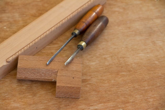
Photo 2 shows the chisels used. the front and side rails are rebated to take a solid pine base board and once the assembly is fully glued, the cove moulding can be routed around the top edge.
The width dimension for the gables is taken directly from the completed base allowing for a 2mm set-back from the cove moulding. The gables are of simple frame and panel construction made from 38mm thick members joined with loose tenons. once the decorative chamfer to the front stile is cut, the rails and stiles can be glued and left to dry.
The centre panels were resawn from a single board to yield two matching panels 12mm thick that are held in place with plain mouldings to the rear, and a detailed bolection moulding to the front face. Finally, cut the 6mm mortises in each gable for the tenons on the two rails that will support the drawer and drop front door. once the gables are complete they are dowelled and screwed to the rails of the base assembly with two 75mm screws.

The top assembly is really a feature of the cabinet. Photo 3 shows the components which include a base board, internal framing and a top board with cantered corners and carved detail.
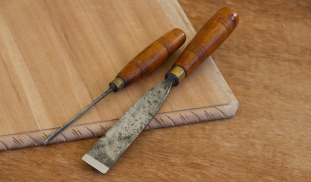
The rope edge carving to the top is cut with two chisels only, a 25mm No.2 and a 4mm No.11 as shown in photo 4. It is important the dimensions for the top assembly are taken from the assembled gables and base frame to ensure an accurate match.
The rails supporting the drawer and drop front door can now be cut. As shown in fig.2, the rail supporting the drop front requires a carefully cut cove to allow the door to hinge unobstructed. I strongly recommend you complete a full scale drawing of all components involved in the hinged drop front to guide you through this detailed work as all pieces need to be cut very accurately.
I also cut a prototype bottom rail for the drop front door and tested this on the assembled hinges before cutting the final door components. With the rails between the gables complete, the carcase can be glued and clamped into final position.
Back panel, doors and drawers the solid frame and panel back can now be cut, assembled and glued before screwing it into position for bracing. the doors and drawers are of conventional construction. cockbeading was added to the front drawer via the traditional method of rebating the drawer front in keeping with the 18th century styling.
Fig.2 provides the dimensions of the rails and stiles including rebates for both the front panel and the rear panel that will become the writing surface. If you intend to fit leather to the writing surface, the panel will need to be thicknessed to 1mm below the level of the surrounding door rails and stiles to allow for the leather.
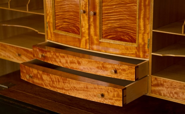
Internal desk gallery the internal fitout of the desk (photo 5) is really where the fun starts. this is best constructed as a single assembly that can be slipped in from the rear as shown in photo 6.

The design was taken from the magnificent Jubilee Cabinet commission made by english master craftsman ed Barnsley in the 1970s. once again, a detailed full size drawing will best guide you through the construction of this unit. Fig.5 gives the overall dimensions.

The outer frame functions as the door stop for the drop front and an inner mitred frame into which the dividers are rebated. Photo 7 shows an example of one of the shaped 4mm thick dividers along with the scratchstock used to work its edges. The scratchstock beading cutter is simply filed from an old bandsaw blade and worked along the grain.
Choose nice straight grained boards for this, as scratchstocks do not like highly figured timber. In the photo you can also see the opposite end of the scratchstock cutter is filed to a double bead. this is the end of the cutter that is used to shape the thicker 8mm frames into which the dividers slide.
The last 30mm of the divider is finished with a 45° mitre which is cut on the router table with two passes against a chamfer bit. this mitre is critical to the success of constructing the gallery and the quality of fit.
The dividers slide along shallow rebates cut into the 8mm framing. the width of the rebates is set to the exact thickness of the divider and the rebate depth needs to match the depth of the 45° mitred section. the rebates in the framework are stopped short to allow the final 25mm to be routed with a 45° V-cutter, again to an exact matching depth of the mitred section of the divider.
Run some test pieces to get the rebate depths correct as the accuracy needs to be close to perfect for the fit to look professional. the other trick here is to select the router bit to be used for the rebates prior to machining any dividers or framework pieces.
the dividers need to be machined to the exact thickness of the rebate cutter (4mm) and the framing members to fig.5: Drawer and shelf layout double this thickness or you will have a lot of difficult hand work to get the pieces to fit.
The final routing task in building the desk gallery is to cut an arced rebate into the outer side frames to take the brass quadrant desk stays when the drop front is closed (fig.3). Ensure the arc is centred from the location of the hinge pin rather than the corner of the gallery side. I tried to purchase these stays but eventually gave up. the best $70 I have ever spent was having the desk stays cut from sheet brass by a local laser cutting company. this saved me untold hours and provided superb accuracy.
The top end of the stays were thickened to double the thickness of the brass plate by screwing an offcut to the main brass section. It is this double thickness that bottoms out against the stile of the main carcase gable to provide support for the drop front when open.

The thin dividers are best cut from quartersawn material for stability. I used some lovely Qld white beech as a contrast to the figured silkwood. Be prepared for the desk gallery to take as long or longer to make than the remainder of the entire piece as there is so much detailed fitting to be done. Features like the bow fronted central drawers and doors along with the bookmatched veneers to the drawer fronts add to the overall quality of the piece.
Republished from Australian Wood Review, issue 80.
Troy McDonald is a regular contributor to Australian Wood Review magazine.