Folding Ladder
Canadian woodworkers Charles Mak and Chris Wong—living 1,000 km apart—teamed up to produce this unique folding ladder, shown fully open at the bottom of this page.
When the ladder is closed the rungs pivot and hide themselves inside grooves milled into the stiles. Based on a similar folding ladder Charles Mak has had for many years, co-author Chris built a shorter version to share the building process and techniques.
This project moves through the typical furniture making steps, and as always, accurate marking and layout work is the foundation for success. We chose ash, a resilient wood, to make the ladder for its strength, durability and ease to machine. Hickory and oak are other suitable choices. The stiles can be made of lighter wood to keep down the weight of a longer ladder.
In Australia eucalypt (Tas oak or Vic ash) species would be suitable. Regardless of the species chosen, use wood that is as straight-grained as possible and with minimal run-out, especially for the rungs and pegs.
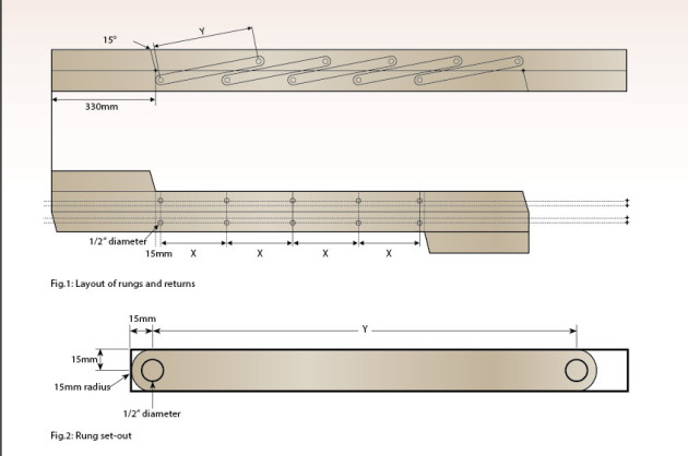
Measured drawings
You are free to make cosmetic changes to the design, but we strongly suggest that you adhere to the measurements given in Figs 1–4. For a longer ladder, increase the stile length in increments of 207mm for each additional rung.

Stock preparation
This ladder consists of two stiles, five rungs, and two returns. The returns are cut from the ends of the stiles to ensure grain continuity.
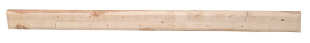
First, cut the rough stock along the grain into two long stiles and joint the mating edges using a hand or power plane (photo 1). A tight fit between the stiles when they are closed shows good craftsmanship.
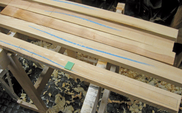
We used a clear plastic template to lay out the rungs parallel to the grain (photo 2). Mill the rungs to final thickness and width but over-length by about 12mm; later they will be cut to exact length. For the pegs, you can use commercial pre-cut 12.5mm dowels or make your own from a contrasting wood. We used a dowel cutter to make our pegs. Whatever you use for pegs, make them a little longer than the stiles are thick and chamfer one end to ease entry.

Rout the grooves
We found it easier to handle and mill the grooves in the stiles, which are stopped at one end, with a hand held router instead of on a router table or tablesaw. The 45mm deep grooves are cut wide enough to allow the rungs to slip in without force, yet not be sloppy. Make two passes with a ½” up-spiral bit and a fence (photo 3). You can also laminate pieces to form the stiles and the grooves. The stopped ends of the grooves are squared up using a chisel.

Cut and align the returns

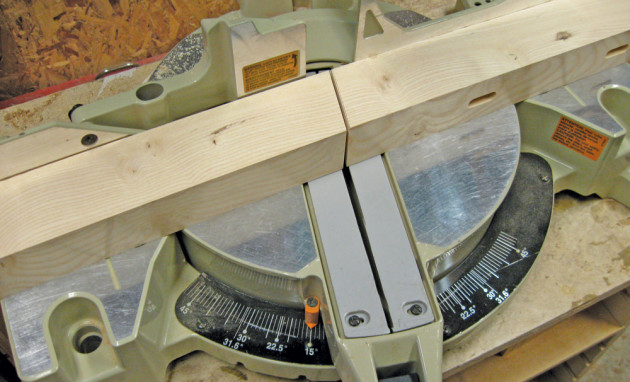
Measure 330mm from one end of each stile and make the 15° mitre cut as shown in Fig.1 and photo 4.
We used dominos to align and attach the returns to the stiles temporarily (photo 5). You can use floating tenons or splines or just clamps (no glue) for the temporary attachment.

Lay out the positions of the rungs
Temporarily clamp the two stiles back-to-back to aid in laying out the rung positions (photo 6).

Begin by laying out a pivot-hole baseline in the stiles, using a combination square set to 30mm and scribing a pencil line the length of the groove. With the square end of the return set flush with the end of the stile, use a square to transfer a line across both stiles at the tip of the return. Offset this line by half the width of a rung and repeat this process at the other end. The intersection between marks and the baseline drawn with the combination square are the positions of the two end pivots. Then, evenly space the remaining pivot points (‘X’ on fig.1) by stepping a pair of dividers along the pivot-hole baseline.
Drill the pivot points
With the positions of the rungs laid out, mark the midpoint of each rung’s width along the pivot-hole baseline. Later, you will drill 12.5mm holes at these marks. (photo 7).

Lay the stiles in the closed position and measure the distance from one centre point to the corresponding one. This is the centre-to-centre measurement (‘Y’ in the diagrams) for the rungs (photo 8). To this measurement, add the width of the rung which is 30mm and cut all the rungs to this length. Lay out the centrepoints (for drilling 33/64” centered holes) along the pivot-hole baseline in the middle of each rung’s location.

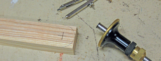
Using a marking gauge, mark centrepoints for the 33/64” pivot holes in the rungs. They are located 15mm from each end and centered on the rung’s width. From the centre point, use a compass to draw a bullnose profile on each end (photo 9), then shape the end. Drill 33/64” diameter holes in all the rungs to accept the ½” diameter pegs. If you don’t have a 33/64” bit, you can use a 1/2” bit and open the hole up by using a dowel wrapped with sandpaper or a round file so the pegs don’t bind.
Fit the rungs and pegs
Set a rung in the groove, align the holes and drive the peg through the hole. (To make driving the pegs easier, we put the pegs in the microwave, two at a time, for about 10 seconds to shrink their diameter a hair.) Then swell and lock the peg with glue (photo 10). After the glue is dried, flush trim all the pegs on both sides and remove any squeeze-out.

Fit the returns flush with the stiles
After all the rungs are installed, test the movement of the ladder and position the returns such that they do not interfere with the range of motion. Glue and clamp them in place (photo 11).

After the glue is cured, open the ladder fully (so that the rungs are perpendicular to the stiles) and draw a straight perpendicular line on each return end that aligns with the mitred end of the opposite stile (photo 12). Trim both return ends on the straight lines on a mitre saw.

Shape the stile profile and ease the edges
To lighten the ladder and soften the look, we used a low-angle bevel router bit to chamfer the stile faces (photo 13). Then we eased all the edges and sanded the ladder with 120, 180, and 220 grit sandpaper.

Fit locking mechanism and non-slip end caps
The stiles are folded together when not in use. We’ve left the locking design for you to create, perhaps using a simple hook and eye, a fancy latch or some creative use of magnets. In addition, if you plan to use the ladder on a potentially slippery surface such as a hardwood floor, add angled non-slip rubber pads as end caps to the stiles to grip the floor.
Finishing
Apply only a clear protective finish to the ladder so it can be regularly inspected for cracks or damage. We sprayed on five coats of satin polyurethane covering the entire ladder. Some parts such as the rungs and the hard-to-access insides of grooves were pre-finished before assembly. An oil finish, such as boiled linseed oil, is another choice but be aware that oils with additives can conduct electricity.
Ever feel outdone by your woodworking mates? Turn the tables: bring out this useful conversation piece in its locked position and challenge them to figure out what you’ve built!
Charles Mak, a semi-retired businessperson in Alberta, Canada, enjoys writing articles, authoring tricks of the trade, teaching workshops, and woodworking in his shop. Email Charles at: thecanadianwoodworker@gmail.com
Chris Wong, owner of Flair Woodworks and Time Warp Toolworks in British Columbia, Canada, teaches and writes about woodworking and toolmaking in addition to making sculptural furniture. Chris can be contacted via
chris@flairwoodworks.com
Cutting List
Stiles and returns: 2 of 1830 x 130 x 42mm [includes 3mm kerf waste]
Rungs: 5 of 370 x 30 x 20mm
Pins: 10 of 55 x 12 x 12.5mm dowel

